Fieldbus devices require far more attention in their initial setup and commissioning than their analog counterparts. Unlike an analog transmitter, for example, where the only “configuration” settings are its zero and span calibration adjustments, a FF transmitter has a substantial number of parameters describing its behavior. Some of these parameters must be set by the end-user, while others are configured automatically by the host system during the start-up process, which we generally refer to as commissioning.
Configuration files
In order for a FF device to work together with a host system (which may be manufactured by a different company), the device must have its capabilities explicitly described so the host system “knows what to do with it.” This is analogous to the need for driver files when interfacing a personal computer with a new peripheral device such as a printer, scanner, or modem.
A standardized language exists for digital instrumentation called the Device Description Language, or DDL. All FF instrument manufacturers are required to document their devices’ capabilities in this standard-format language, which is then compiled by a computer into a set of files known as the Device Description (DD) files for that instrument. DDL itself is a text-based language, much like C or Java, written by a human programmer. The DD files are generated from the DDL source file by a computer, output in a form intended for another computer’s read-only access. For FF instruments, the DD files end in the filename extensions .sym and .ffo, and may be obtained freely from the manufacturer or from the Fieldbus Foundation website (http://www.fieldbus.org). The .ffo DD file is in a binary format readable only by a computer with the appropriate “DD services” software active. The .sym DD file is ASCII-encoded, making it viewable by a human by using a text editor program (although you should not attempt to edit the contents of a .sym file).
Other device-specific files maintained by the host system of a FF segment are the Capability and Value files, both referred to as Common Format Files, or .cff files. These are also text-readable (ASCII encoded) digital files describing device capability and specific configuration values for the device, respectively. The Capability file for a FF device is typically downloaded from either the manufacturer’s or the Fieldbus Foundation website along with the two DD files, as a three-file set (filename extensions being .cff, .sym, and .ffo, respectively). The Value file is generated by the host system during the device’s configuration, storing the specific configuration values for that specific device and system tag number. The data stored in a Value file may be used to duplicate the exact configuration of a failed FF device, ensuring the new device replacing it will contain all the same parameters.
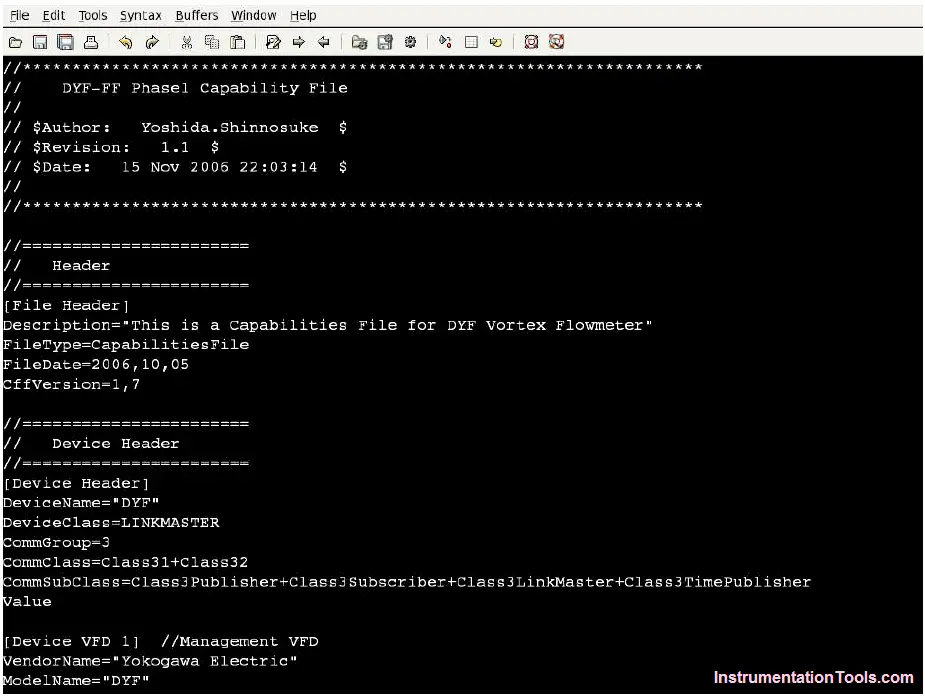
A screenshot of a .cff Capability file opened in a text editor program appears here, showing the first few lines of code describing the capabilities of a Yokogawa model DYF vortex flowmeter:
As with “driver” files needed to make a personal computer peripheral device function, it is important to have the correct versions of the Capability and DD files installed on the host system computer before attempting to commission the device. It is permissible to have Capability and DD files installed that are newer than the physical device, but not vice-versa (a newer physical device than the Capability and DD files). This requirement of proper configuration file management is a new task for the instrument technician and engineer to manage in their jobs. With every new FF device installed in a control system, the proper configuration files must be obtained, installed, and archived for safe keeping in the event of data loss (a “crash”) in the host system.
Device commissioning
The commissioning of a Fieldbus device on a real segment, showing screenshots of a host system’s configuration menus. The particular device happens to be a Fisher DVC5000f valve positioner, and the host system is a DeltaV distributed control system manufactured by Emerson. All configuration files were updated in this system prior to the commissioning exercise. Keep in mind that the particular steps taken to commission any FF device will vary from one host system to another, and may not follow the sequence of steps shown here.
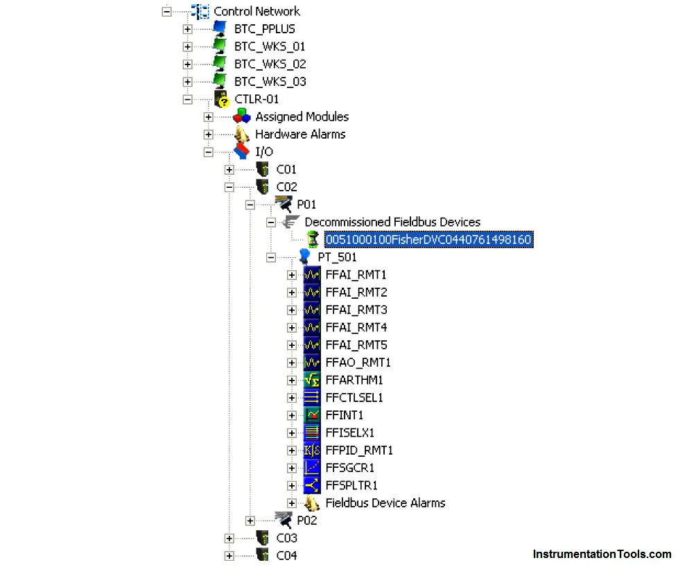
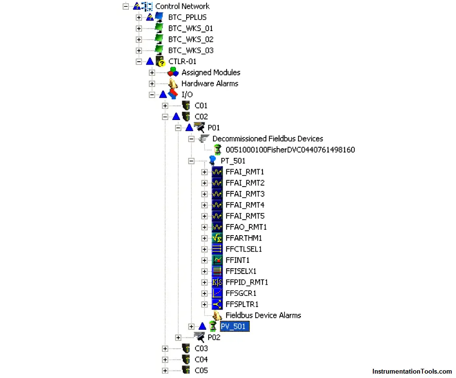
If an unconfigured FF device is connected to an H1 network, it appears as a “decommissioned” device. On the Emerson DeltaV host system, all decommissioned FF devices appear within a designated folder on the “container” hierarchy. Here, my Fisher DVC5000 device is shown highlighted in blue. A commissioned FF device appears just below it (PT 501), showing all available function blocks within that instrument:
Before any FF device may be recognized by the DeltaV host system, a “placeholder” and tag name must be created for it within the segment hierarchy. To do this, a “New Fieldbus Device” must be added to the H1 port. Once this option is selected, a window opens up to allow naming of this new device:
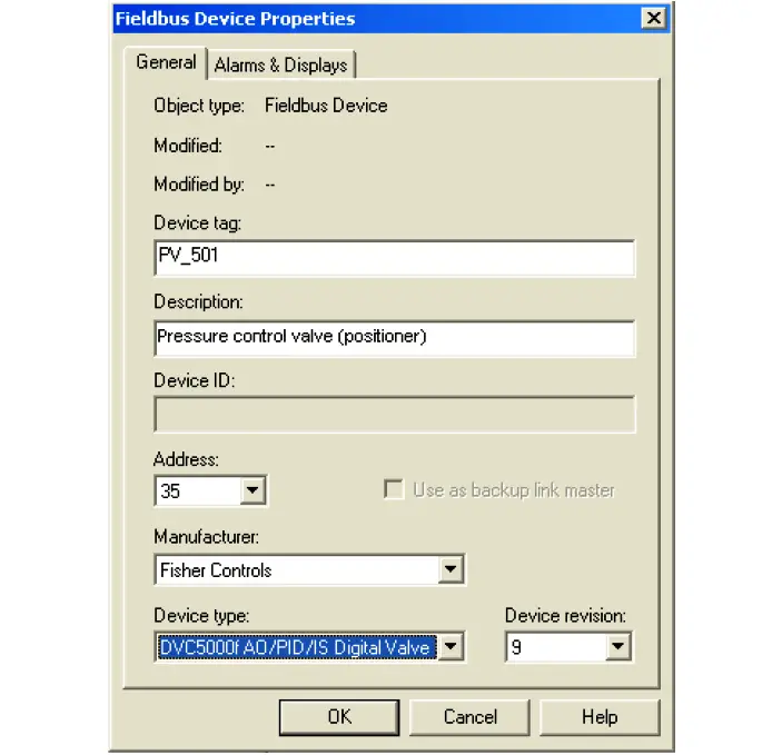
Here, the tag name “PV 501” has been chosen for the Fisher valve positioner, since it will work in conjunction with the pressure transmitter PT 501 to form a complete pressure control loop. In addition to a tag name (PV 501), I have also added a text description (“Pressure control valve (positioner)”), and specified the device type (Fisher DVC5000f with AO, PID, and IS function block capability). The DeltaV host system chose a free address for this device (35), although it is possible to manually select the desired device address at this point. Note the “Backup Link Master” check box in this configuration window, which is grey in color (indicating the option is not available with this device).
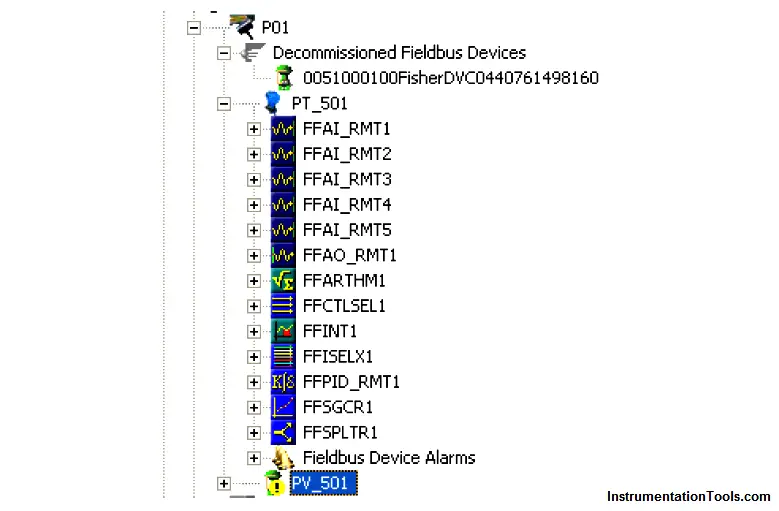
After the device information has been entered for the new tag name, a “placeholder” icon appears within the hierarchy for the H1 segment (connected to Port 1). You can see the new tag name (PV 501) below the last function block for the commissioned FF instrument (PT 501). The actual device is still decommissioned, and appears as such:
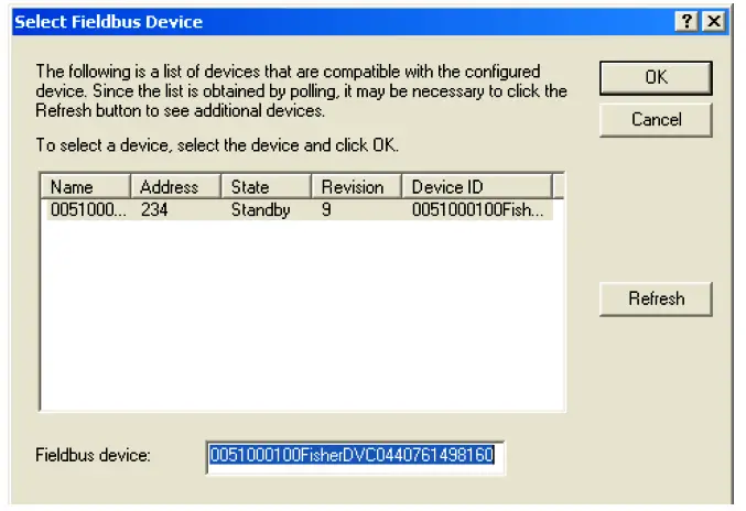
By right-clicking on the new tag name and selecting the “Commission” option, a new window opens to allow you to select which decommissioned device should be given the new tag name. Since there is only one decommissioned device on this particular H1 segment, only one option appears within the window:
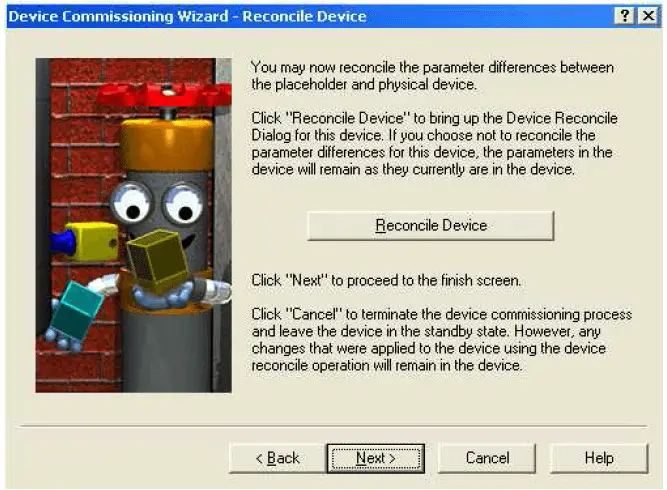
After selecting the decommissioned device you wish to commission, the DeltaV host system prompts you to reconcile any differences between the newly created tag name placeholder and the decommissioned device. If you want to use the existing values stored within the physical (decommissioned) device, you skip the “reconcile” step. If you want to alter the values in the device from what they presently are, you choose the “reconcile” option which then opens up an editing window where you can set the device values however you wish.
After selecting (or not selecting) the “reconcile” option, the DeltaV system prompts you to confirm commissioning of the device, after which it goes through a series of animated display sequences as the device transitions from the “Standby” state to the “Commissioned” state:
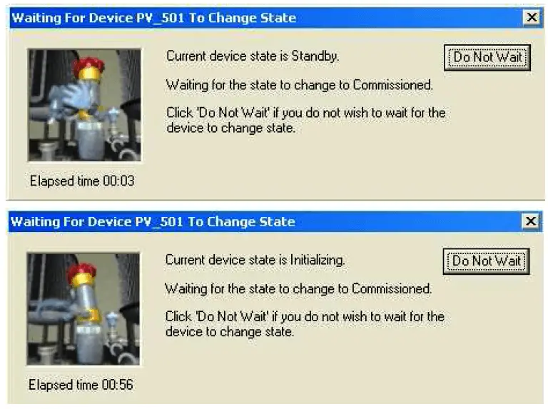
As you can see, the commissioning process is not very fast. After nearly one full minute of waiting, the device is still “Initializing” and not yet “Commissioned.” The network speed of 31.25 kbps and the priority of scheduled communications are limiting factors when exchanging large quantities of configuration data over a FF H1 network segment. In order for device configuration to not interrupt or slow down process-critical data transfers, all configuration data exchanges must wait for unscheduled time periods, and then transmit at the relatively slow rate of 31.25 kbps when the alloted times arrive. Any technician accustomed to the fast data transfer rates of modern Ethernet devices will feel as though he or she has taken a step back in time when computers were much slower.
After commissioning this device on the DeltaV host system, several placeholders in the hierarchy appear with blue triangles next to them. In the DeltaV system, these blue triangle icons represent the need to download database changes to the distributed nodes of the system:
After “downloading” the data, the new FF valve positioner shows up directly below the existing pressure transmitter as a commissioned instrument, and is ready for service. The function blocks for pressure transmitter PT 501 have been “collapsed” back into the transmitter’s icon, and the function blocks for the new valve positioner (PV 501) have been “expanded” for view:
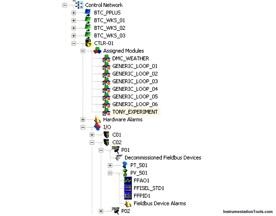
As you can see, the new instrument (PV 501) does not offer nearly as many function blocks as the original FF instrument (PT 501). The number of Fieldbus function blocks offered by any FF instrument is a function of that instrument’s computational ability, internal task loading, and the discretion of its designers. Obviously, this is an important factor to consider when designing a FF segment: being sure to include instruments that contain all the necessary function blocks to execute the desired control scheme. This may also become an issue if one of the FF instruments in a control scheme is replaced with one of a different manufacturer or model, having fewer available function blocks. If one or more mission-critical function blocks is not available in the replacement instrument, a different replacement must be sought.