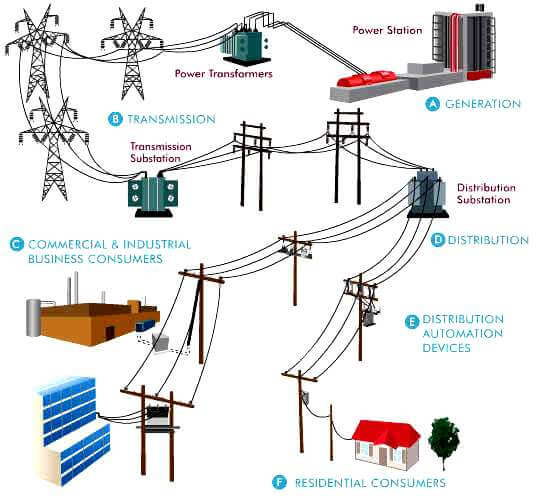
Electricity distribution is the final stage in the delivery of electricity to end users. A distribution system’snetwork carries electricity from the transmission system and delivers it to consumers. Typically, the network would include medium-voltage (1kV to 72.5kV) power lines, substations and pole-mounted transformers, low-voltage (less than 1 kV) distribution wiring and sometimes meters.
History
In the early days of electricity distribution, direct current (DC) generators were connected to loads at the same voltage. The generation, transmission and loads had to be of the same voltage because there was no way of changing DC voltage levels, other than inefficient motor-generator sets. Low DC voltages (around 100 volts) were used since that was a practical voltage for incandescent lamps, which were the primary electrical load. Low voltage also required less insulation for safe distribution within buildings. The loss in a cable is proportional to the square of the current, and the resistance of the cable. A higher transmission voltage would reduce the copper size to transmit a given quantity of power, but no efficient method existed to change the voltage of DC power circuits. To keep losses to an economically practical level the Edison DC system needed thick cables and local generators. Early DC generating plants needed to be within about 1.5 miles (2.4 km) of the farthest customer to avoid excessively large and expensive conductors.
ELECTRICAL DISTRIBUTION SYSTEMS
Introduction to the course: this course is provided in a question & answer format and is divided into 5 chapters, it will become extremely useful to you:
• If you want to know the parameters of the induction motors, their effect on the starting and normal performance of the machine.
• If you want to analyze an existing a.c. machine or evaluate a new one for its steady state or transient state including starting and short circuit.
• If you want to know the major components in the power distribution systems and how each component is defined.
• If you want to calculate the line and cable constants from the information found in standard tables.
• If you want to know the different types of breakers, starters and switchgear assemblies. Also, if you want to know how they are defined.
• If you want to do the necessary calculations to size the load breaking/interrupting/disconnecting devices for normal and fault conditions.
• If you want to know the types and sources of power line disturbances. Also, if you want to know the effects of such disturbances on the major components of the power systems and the methods of reducing these damaging effects.
• If you want to know the effects of using local capacitors in increasing the circuit capacity anyhow to size capacitors to improve the p.f. in motor circuits.
• If you want to quantify the effect of direct and indirect lightning strokes on overhead distribution systems.
• If you want to know what are the data that have to be available in order to perform any of the following studies: TRV, stability, load flow, fault/co-ordination, motor starting, reliability and switching transients.
• If you to know the procedure to calculate the following: basic values including base and p.u.values, load flow, fault current/voltage sensitivity, motor starting, reliability studies for simple radial systems.
• If you want to know how steel properties, switchboard instruments, meters, relays are defined and what are the major modules of PLC plus the building blocks of an office automation system.
• If you want to know the calculations to be performed if a major power transformer is to be protected against short circuits or overloads.
• If you want to know what are the essential programs and data for the power systems analyst (or any other individual involved in electric power distribution and studies – for that matter).
Questions & Answers :
Electric power distribution system?
The electricity supply system is divided into the transmission system and thedistribution system. The distribution system is the part of the system which supplies the consumer -in the UK, we are talking about voltages of 33 kV, 11 kV, and 400/230 V.
What is the role of Global Distribution Systems?
A computer reservations system or central reservation system CRS is a computerized system used to store and retrieve information and conduct transactions related to air travel. Originally designed and operated by airlines, CRSes were later extended for the use of travel agencies. Major CRS operations that book and sell tickets for multiple airlines are known as global distribution systems (GDS).
What is low voltage distribution system?
In the Typical sense its anything 50 volts or below. When speaking of service voltages its 600 volts or below. The threshold of 50 volts is believed to be the point where skin will resist shock so a lessor hazard is encountered.
What is the purpose of electrical distribution system?
Exactly what it sounds like. It is used to get electricity from the generation plant to the customers. It can consist of many different voltage levels.
What is the meaning of feeder in electrical distribution systems?
Feeders are conductors which connect the consumers with the sub-station. Tapings to feed current to the consumers are NOT taken from the feeders. Therefore, its current loading remains the same alo
What is the first phase of installing the BEAR electrical distribution system?
providing mission essential power
What is meaning of distribution in electrical power system?
Distribution means taking the Electrical power to different usage points where power is needed
List possible symptoms of a problem with the electrical system of a PC?
1. Memory errors, data errors, brownouts, or reboots are symptoms of electrical system problems.
The classification of EPR (up to 35KV) cables is as follows: the voltage class, the conductor material/size (which is function of the normal/overload/short circuit current values and the installation method/configuration), the insulation thickness (whether 100% or 133%), jacketed or unbracketed, neutral size (either full or 1/3 rating), cable in conduit configuration/direct buried or concrete encased conduits.2) How would underground XLPE (cross linked polyethylene) cables classified?The classification of XLPE (up to 46KV) cables is as follows: the voltage class, the conductor material/size, insulation thickness, jacketed or unbracketed, neutral (concentric neutral and rating full or 1/3 main conductor) or shielded (Cu tape), single or 3-conductor cables, jacket-type(whether encapsulated or sleeved), the use of strand-fill or water blocking agent between the insulation and jacket.
3) What are the defining parameters of cables?
The defining parameters can be classified broadly into dimensional, insulation material properties and current carrying capacity. For dimensional parameters, conductor size/number of strands/type of strands, diameter over conductor, diameter over insulation, diameter over insulation screen, number and size of neutral conductors or tape details (thickness, width & lap type) and diameter over the jacket are the defining data. Other important data are: weight/1000 ft length, size of reels and length/reel. The insulation/jacket defining parameters are: before an dafter aging tensile strength and elongation, hot creep elongation/set, dielectric constant,capacitance (SIC) during and after the stability period, insulation resistance constant, water absorption properties. The last set of defining parameters are the current levels at the nominal voltage under the different operating conditions which are function of: the layout and proximity of current carrying cables, the method of laying/pulling of cables, provision of future additional loads with their corresponding maximum allowable voltage drop and finally the maximum acceptable temperature rise & duration for the cable insulating material.
4) What are the factory and site tests to be performed on cables?
The different types of tests that are performed on cables at the factory are: partial discharge, DC resistance of central conductor, AC high voltage dielectric withstand ability, DC high understandability, insulation resistance, physical dimensions of cable components, cold bend, low temperature impact, jacket integrity, water penetration and high temperature drip test for the-strand fill (if applicable). For conductor shield the tests are: volume resistivity, elongation at rupture, void and protrusions, irregularities verification. For the insulation are: tensile strength(aged and unwaged)/elongation at rupture (aged and unwaged)/dissipation factor (or power factor)/hot creep (elongation and set)/voids and contamination/solvent extraction (if applicable).For the insulation shield are: volume resistivity/elongation at rupture/void and protrusions irregularities/strippability at room temperature and at -25C/water boil test. For the jacket are:tensile strength, elongation at rupture (aged and unwaged), absorption coefficient (of water), heat shock and distortion. On the cable the following tests may be performed: structural stability and insulation shrink back for certain insulation materials. The tests performed on site are: visual inspection, size/ratings verification and D.C. withstand ability tests at voltage level below those used in the factory.
5) What are the defining parameters for low voltage secondary cables?
The defining parameters for l.v. secondary cables are: material of phase conductor, number of strands, class of strand, type of conductor (ie. concentric, compact or compressed), conductor size, insulation thickness, over all diameter per cable, overall diameter per assembly (ie. triple xor quadruples), the neutral conductor size (equal to the phase or reduced), if applicable,insulation and jacket materials, jacket thickness and the weight per assembly per 1000 ft length.
6) What are the different types of transformers found in distribution systems?
The different types of transformers found in distribution systems are: Power (up to 10MVA)liquid filled (oil), power (over 10 up to 100 MVA) oil filled with radiators/fans (one or 2 sets),single phase distribution transformers/oil filled (with or without radiators/fans) up to 500 KVA,three phase distribution transformers/oil filled (with or without radiators/fans) up to 1.5MVA,dry type power transformers/3 phase 300 KVA to 2MVA or silicone filled or epoxy resin insulated for indoor installations. All oil filled transformers are installed outdoor unless special layout with fire proof (resisting) material and appropriate barriers are used, then indoor installation is possible. Distribution transformers can be of the pole mounted, vault surmounted type. The primary voltage of power transformers can be as high as 750 KV, though the most common are 345KV, 220KV, 115KV, for distribution transformers as high as 72KVthough the most common are 34.5, 25KV (27.6KV), 15KV.
7) What are the different types of overhead switches, pad mounted switchgear and those of lightning arresters?
The different types of overhead switches are: either single or three phase, either manually operated or electric/manual operated, either local control or remote/local control, oil insulated or air or SF6. The different types of pad mounted switchgear are: either manually or manually/motor operated, controlled locally or locally/remotely, air or oil or SF6/vacuum insulated, protective devices are either fuses or electronic devices. The configuration will,generally, have four compartments with any combination of fuse or interrupter, switch, solid or empty compartment. The different types of lightning arr esters are: station, intermediate,distribution (heavy duty, normal or light duty) and may be riser pole type.
8) What are the standards that govern distribution transformers? How are distribution transformers defined?
The standards that govern distribution transformers are: CSA “Single phase & three phase distribution transformers” Std. C2, CSA “Dry type transformers” C9, CSA “Guide for loading Dry-type distribution and power transformers” C9.1 and CSA “Insulating oil” C50. The distribution transformers are defined as follows: the voltage ratings (insulation class level of primary -h.v.- winding, the primary and secondary windings rated voltage), short circuit capability for a fault on the bushings of the transformer (current value and its corresponding duration), dielectric test values (applied voltage for 1 minute, full wave and chopped BIL anytime to flash over for the chopped), outdoor transformer bushings ratings (defined by their insulation class, 60HZ 1 minute/dry, 10 second/wet dielectric withstand ability, the full wave and chopped BIL), audible sound levels and induced voltage tests.
9) How are wooden and concrete poles defined?
The wooden poles are defined as follows: the class (1 to 7-4500LB to 1200 minimum horizontal breaking load when applied 2 ft. from pole top), the minimum circumference at pole top level(27″ to 15″), length of pole (25 to 110 ft, generally), minimum circumference at the ground level(distance from butt), the wood species (Western Red Cedar, Southern Yellow Pine, Douglas Fir,Western Larch), the treatment against attack from fungi and insects (eg. creosote oil, ammonicalcopper fatty acid, pentachlorphenol or chromated copper arsenates) and the weight per pole.The concrete poles are defined accordingly: ultimate load (class A to J, 600 LB to 4500 LB,respectively), the length, the manufacturing process (regular or prestressed class), the steelreinforcing rods (cage) tensile strength, the diameter, the raceway diameter, spacing anddiameter of holes in the pole, grounding bars (galvanized or coated) surface treatment.
10) What are the different applications of oil switches and what are their defining parameters?
The different applications of overhead oil switches in utility distribution systems are: generalpurpose for inductive and resistive loads & capacitor (capacitive current switching). Thedefining parameters are: the rated maximum voltage, the basic impulse level, the dielectric withstand, continuous current, inductive load switching, capacitive switching current, makingcurrent, momentary current, short time current rating; for the control circuit: nominal and rangeof operating voltage, trip coil current. The weight, dimensions, oil volume and speed of operation for the switch are also important defining data. The other two devices that may use oilas the switching medium are the sectionalizes and reclosers.
11) How are overhead air switches classified?
The following is the classification of the air insulated switches according to their breaking type:side break switches, vertical break and double break. The different types of mountings for suchswitches are: upright, vertical, triangular, tiered outboard mounting and pedestal. The insulatorsof the switch may be epoxy or porcelain, the base is insulated or steel.
13) What are the important parameters by which lightning arresters are defined?
14) How would copper conductors be defined?
The construction of copper conductors is defined as follows: cross section area, class of conductor (indication of degree of flexibility), number of wires, diameter of wire, tensilestrength, elongation, diameter of conductor, type (concentric lays, compact or compressed) andweight per 1000 ft.
15) How would ACSR (aluminum conductor steel reinforced) and ASC (aluminumstranded conductor) be defined?
The defining parameters for aluminium conductor steel reinforced designs are: the Al area, thetotal conductor area, steel/Al area ratio, number of Al wires, diameter of Al wire, area of steelwire, diameter of steel wire, diameter of core (steel), diameter of conductor, tensile strength,AWG size, total conductor weight per 1000 ft. and the ratio of Al weight to the total weight. Thedefining parameters for aluminium stranded conductors are: the aluminum conductor area, thequantity (number) of Al wires, diameter of each wire, the diameter of the conductor, the tensilestrength, the elongation and the total weight of conductor per 1000 ft.
16) How would AASC (aluminum alloy stranded conductor) and self-dampening/compact ACSR be defined?
The defining parameters for Aluminium alloy stranded conductors are: Al alloy area and theequivalent Al area, number of Al alloy wire, diameter per wire, overall diameter of conductor,AWG/KCMIL, weight/1000 ft, tensile strength and elongation. The defining parameters for self-dampening conductors and compact ACSR are: aluminium area, total conductor area, steel to Alarea (ratio), number of Al wires, number of steel wires, core (steel) diameter, overall conductordiameter, conductor weight/1000 ft length, ratio of Al weight to total weight, tensile strengthand elongation.
17) What are the different types of cable splices and terminations?
The different types of cable splices are: tapped, heat shrinkable and cold shrinkable. The majorcomponents of a splice are: cable adapters, splice housing, conductor contact, conductive insert,retaining rings/tube, interference fit and grounding eye. The different types of cableterminations are: the fully taped, moulded stress cone and tape, one piece moulded cabletermination, porcelain terminators, heat shrinkables and potheads.
18) What are the different types of connectors and elbows?
The different types of connectors are: the mechanical (for Al and/or Cu conductors), thecompression, the wedge (to connect main conductors to taps), hot line clamps (the mainoverhead to equipment connection) and the stirrups (wedged or bolted). The two types of separable connectors (elbows) are the dead break and load break. The major components of elbows are: the connector, the moulded insulating body, cable adapter, the test point, the semi-conducing shield, semi-conducting insert, grounding tabs the pulling eye, the probe (for loadbreak, it is field replaceable with abelative material arc follower).
19) What are the design tests performed on the separable connectors?
The design tests performed on the elbows are: partial discharge inception and extinction levels(corona), withstand power frequency voltage capability (a.c. and d.c.), impulse voltagewithstand level, short time current rating, switching test, fault closure rating, current cycling forinsulated and uninsulated connectors, cable pullout from elbow (connector), operating force,pulling eye operation, test point cap pulling test, shielding test, interchangeability, acceleratedthermal and sealing life, test point capacitance (voltage presence indication) test.
20) What are the different types of insulators, their material and characteristics?
The different types of insulators are: the pin, the suspension and the post (vertical andhorizontal). The different insulators materials are: porcelain, glass, fibreglass, polymer andsilicone. The properties of insulators can be broadly classified into: mechanical, electrical,environmental and maintenance. The mechanical can further be classified into: different loadsthe insulators is subjected to due to weights of supported components, short circuit, ice, etc.(normal, design, cyclic, torsional, overloads – exceptional), safety factors, single or multipleinsulator assemblies and aging effect on strength of insulator. The electrical parameters definingthe insulators are: BIL, power frequency withstandability (dry, wet and flashover level), leakagedistance, power arcs effect, performance under steep front voltage wave, clearances andperformance under contamination. The environmental characteristics can be further broke down into: insulator ageing under ultra-violet rays and dry arcing, type of contamination, radiointerference voltage, washing requirements, corrosive environments and temperature range.
21) What are the major information obtained from a distribution system SCADA?Show ablock diagram of the major components of a SCADA (system supervisory control & dataacquisition). Sketch a diagram to show a typical automated distribution system with powerand communication lines.
The major information obtained from a SCADA in a power distribution system are: indications(eg. state change like opening or closing of circuit breakers, load break switches, reclosures,disconnects, operation of a relay or fault indicators) of events or alarms, levels (eg. oil level, tapchanger position, reading from pressure gauges), pulses (eg. energy meter counters),measurands (eg. current, voltage, power reading, temperature of oil or windings, leakagecurrent).
22) What are the basic modules in a PLC (programmable logic controller) system? Sketcha front plate of 2 of the basic modules. Sketch a block diagram showing the interrelation of the major modules.
The basic modules of a PLC system are: the processor, the input/output (they can further beclassified into digital and analog), process control (proportional/integral/derivative), steppermotor, interface modules (they can be further classified into: local and remote, local and remotetransfer, network, network transfer, multimedia network interface, peripheral devices (theyinclude loader/monitor, process control stations, CRT programmers, hand held programmers,tape loader).