The principle of differential pressure level measurement is based on hydrostatic head.
Hydrostatic pressure measurement is the most common means for liquid and interface level measurements. For most applications, differential transmitters are preferred because the range selection is flexible and widely understood.
They are used with open and enclosed vessels. Differential transmitters are usually connected to the side of a vessel or tank with isolation facilities.
Interface liquid–liquid level calculation example
The differential pressure,
DP = hinterface x g x [ ρ2 – ρ1 ] + ρ1 x g x H (Equation [1])
The range is:
- At hinterface = 0 then DP = ρ1 x g x H
- At hinterface = H then DP = ρ2 x g x H
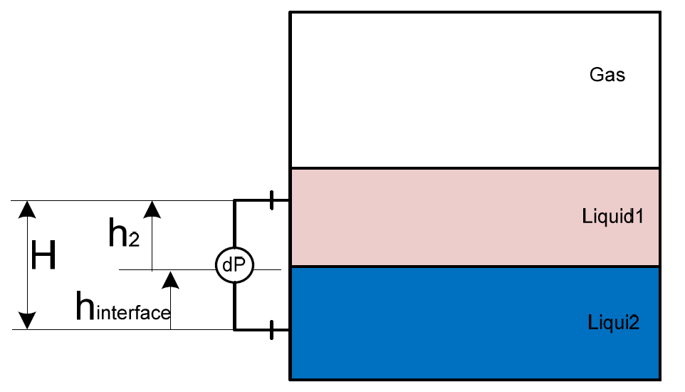
Figure – DP measurement
ρ1 : Liquid1 Density (kg/m3)
ρ2 : Liquid2 Density (kg/m3)
hinterface : Interface Level between the Liquid 1 and Liquid (m)
g: 9.81 (m/s2)
Interface measurement requires its own connection into the upper and the lower phase.
Equation [1] is applicable if there is only one variable. For an interface level measurement it should be hinterface.
Using the same principle and Equation [1], density of a single fluid can be measure if both tapping are permanently and fully immersed.
Following the principle, measurement of several interface layers can be considered by staging each interface level measurement. For an interface measurement between two liquids the limitation is derived from Equation [1].
The combination of density difference and the distance between the upper/lower nozzles should result in a minimum DP range of around 30 mbar.
Limitations
If both density values ρ2 and ρ1 are similar, the interface level measurement may nearly not be detected by the transmitter. This depends on the DP range, accuracy and distance between the upper and lower nozzles. This occurs typically for an interface measurement between oil and water the case of presence of “heavy” oil (the oil density value is nearly the same as the water density value).
Accuracy depends on the liquid density variation. To compensate a density measurement should be provided.
For vessel under vacuum, DP with remote diaphragm seal is recommended. The transmitter should be installed below the bottom nozzle.
For heavy crude oil dirty, foaming, fouling or clogging services the DP with remote diaphragm seal is recommended with nozzle, flushing ring and heat tracing (e.g. freezing oil) as required.
The mounting of heavy instrument (including all accessories, i.e. DBB/SBB valves, flushing ring, etc.) to the nozzles should be verified with the nozzle local stress verification (static and dynamic/fatigue). Sufficient support should be provided for minimizing the weight transferred to the nozzles.
Selection
Differential pressure measurement could be considered for most applications with liquid–gas or liquid–liquid interface level measurement.
Differential pressure transmitters can be used in severely turbulent, dirty, in presence of foam above the liquid or fouling service with diaphragm seals and capillaries.
Differential pressure transmitter with diaphragm seals and capillaries are preferred. This should be provided with a flushing ring mounted between the process flange and the diaphragm seal.
Capillaries should be specified at the correct length, without the need for coiling excess capillary that is surplus to the run. Capillaries should be protected from damage using a basic channel system, allowing sufficient bend radius for the capillaries.
Diaphragm material should be carefully selected according to the type of fluid (e.g. gold plated in presence of hydrogen).
The use of wet legs with intermediate liquids and zero adjustment implies more complex range calculation and higher maintenance needs. Differential pressure transmitter used without diaphragm seals and capillaries should have block and bleed valve manifolds as a minimum. In vapour or cryogenic services, the dry leg should have a self‐purge.
A particular attention should be paid to the protection and heat tracing of dry/wet legs. For capillary tubing, the selection of tubing fluid should consider the ambient temperature (to prevent freezing).
The mounting of heavy instrument (including all accessories, i.e. isolation/drain valves, flushing ring, etc.) on the nozzles should be verified with the nozzle local stress verification (static and dynamic/fatigue). Sufficient support should be provided for minimizing the weight transferred to the nozzles.
High static pressure can create a measurement zero and full scale drift. This can be compensated as required, by measuring and compensating the static pressure.
For low range (e.g. below 300 mm) or similar densities between two liquids (for an interface measurement), a particular attention should be paid to sources of measurement error, such as:
- temperature/density variation of capillary fluid
- measurement resolution error due to 2″ or 3″ nozzle and diaphragm
- zero error due to air/liquid pockets in the hook up/transmitter or fouling of the diaphragm
- uncertainties of the transmitter when maximum possible calibration range of the cell is much greater than actual calibrated range.
1. Impulse piping
For atmospheric vented vessel the low pressure side is connected to the atmosphere. Wind effect or insect should not affect the measurement (e.g. using a bug filter).
The impulse line is used to interface the instrument with the process connection. There are two methods which could be used to connect the instrument the process:
- using a wet leg
- using a dry leg.
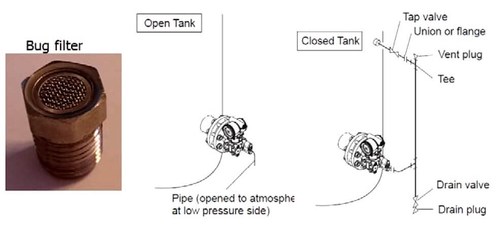
Figure – DP Impulse lines
Wet leg
If the ‘reference leg’ is filled with a liquid, a permanent zero offset will be created. This offset should be compensated.
The wetted leg liquid should be selected for avoiding the risk of evaporation and leakage.
A trifoliate label in the field should be affixed to the three‐way manifold block, highlighting “This level duty is on a wet leg system. Equalization of the transmitter block will result in loss of the wet leg.”
Dry leg
Gas compatibility with the dry leg material should be considered. Gas change state or liquid presence in the dry leg should be carefully addressed.
Where use of Differential Pressure dry leg system are deployed on a closed tank, they should be assessed to ensure no excess fluid or condensate can build up in the low pressure (dry) impulse leg.
Dry legs should include an isolable drainage pot at their lowest point (below HP tap) for allowing the condensates to be drained.
2. Remote diaphragm seal
Diaphragm seal capillaries filled with oil requires a dedicated configuration of the range with a zero drift.
In case of tall measurement range (e.g. above 6 m), two separate remote sensors may be used. The measurement principle is based on a remote sensor replacing the capillaries. In this case, a detailed procedure for the calibration (including the zero shift) should be studied.
For density measurement the liquid should always above the upper nozzle.
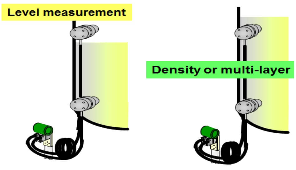
Figure – DP Level vs density measurement
3. Symmetric and asymmetric capillaries
Differential pressure seal system is typically specified with identical capillary lengths and seal configurations on both the high and low pressure process connections. This type of system is traditionally specified because it compensates for temperature induced errors.
The oil volume in the capillary will expand and contract causing fluctuations in the internal pressure of the capillary system. This error will be cancelled out because the same expansion and contraction of oil volume will occur on both the high and low sides of the transmitter due to symmetrical construction.
The second source of temperature induced measurement drift occurs when a capillary seal system is installed with a vertical separation between the two seals. The density of the fill‐fluid within the capillary will fluctuate with the change in temperature and cause the amount of head pressure force that is measured by the transmitter to vary.
Equal lengths of capillary cannot compensate this change in density due to low pressure side generally being mounted at a higher elevation than the high pressure side. An asymmetrical design minimizes the fill‐fluid volume on the high side in order to counteract the temperature induced density effects always present on any vertical installation.
4. Electronic DP level system
This measurement principle is based on independent pressure measurements. Rather than using a single DP transmitter with mechanical impulse piping or capillary, electronic DP level system uses two direct mount gage or absolute sensors that are connected with a non‐proprietary electrical wire.
Electronic DP level system replaces the long lengths of oil‐filled capillary and impulse piping with an electrical wire that is immune to temperature induced effect as well as the lengthy capillary. This means that it will be possible to get an accurate measurement over a large range of ambient temperatures without fill‐fluid density or volume changes affecting the reading. High and low pressure measurements are fully synchronized to ensure that the differential pressure measurement is accurate.
If the ratio between the DP pressure and the vessel static pressure is (DP/Static) < 1/10 the impact on the accuracy will be non‐negligible.
The effect of a static pressure on both side of a non‐electronic DP system implies a drift that needs to be compensated. Electronic DP system calculates and compensates the pressure effect directly without specific calibration.
Electronic DP Level system solves many of the problems that are traditionally seen when making a DP measurement on tall vessels or towers. Typical problems are:
- Mechanical installation constraints : two remote seals + capillaries
- Ambient Temperature effect on the capillaries (fill fluid dilatation/contraction and density variation) results of inaccuracy : insulation or heating tracing of capillaries
- Plugging condensation/evaporation of reference column
- Tall measurement range (e.g. above 6 metre).
Note: One of the two sensors calculates the DP and transmits it back to the host system.
Design
1.Level measurement
DP Transmitter signal variation should be directly proportional to the level variation. HP and LP chamber location (i.e. vessel vs dry/wet legs side) should be studied accordingly. Differential pressure transmitters installed above or below the liquid level range or with dry/wet legs may require a zero shift.
For slurry and/or sludge application extended diaphragm may be used. This would eliminate the dead‐ended cavity typically present in the nozzles installed with standard diaphragm seal and minimize error to measurement. The drawback of this is no isolation valves could be installed due to the extended diaphragm inside the nozzle. Total shutdown and isolation of the tank or vessel may be required to remove the diaphragm for maintenance.
2. Range
Ranges for differential pressure transmitters should be calculated using the minimum following information:
- exact distance between the vessel nozzles
- specific gravity of liquid in vessel according to the temperature and pressure ranges
- specific gravity of upper and lower fluid for transmitters in interface service
- specific gravity of liquid in the reference leg (if applicable)
- Instrument elevation in relation to higher and lower tapping points
- at high operating pressures, zero compensation for gas phase weight/density.
3. Process connection with no diaphragm
Differential pressure transmitters with no remote capillaries seals should have their location as follows:
- keep the impulse tubing as short as possible
- for liquid tapping connection, slope the impulse tubing at least 1 in./foot (8 cm/m) upwards from the differential pressure transmitter towards the vessel connection
- for gas tapping connection, slope the impulse tubing at least 1 in./foot (8 cm/m) downwards from the differential pressure transmitter towards the process connection
- avoid high points in liquid lines and low points in gas lines
- make sure both impulse legs are the same temperature
- use impulse tubing large enough to avoid friction effects and clogging
- prevent sediment deposits in the impulse tubing
- select instrument manifolds with front facing process connections to avoid pockets in the hook up.
On duties that are fouling, a purge to keep the system clear should be used. The purges work with a constant pressure delivered using a rotameter or other similar system, typically with an inert gas.
4. Process connection with diaphragm
Differential pressure transmitters with diaphragm seals and capillaries should be considered taking into account the following consideration.
When flange reducer is necessary, due to a smaller process connection (25 mm or 50 mm) compared to the 75 mm diaphragm, it is recommended to use flushing and draining connections.
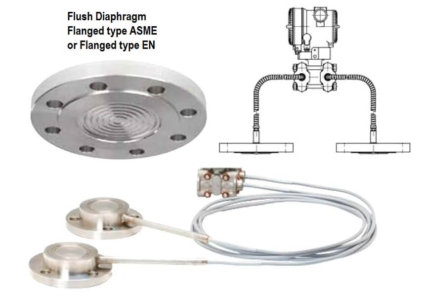
Figure – Process connection with diaphragm
In case there is a risk of freezing liquid in the chamber of the flange adapter/reducer or a high viscosity heat tracing or heating circuit should be considered. Heating medium (steam/oil) should not exceed the fluid boiling point.
Process temperature and ambient temperature should be considered to avoid the fluid boiling or affecting the measurement reaction time (in case of higher fluid viscosity). In a vacuum application this may cause the fluid to reach the boiling point and consequently to blow up the diaphragm and destroy it.
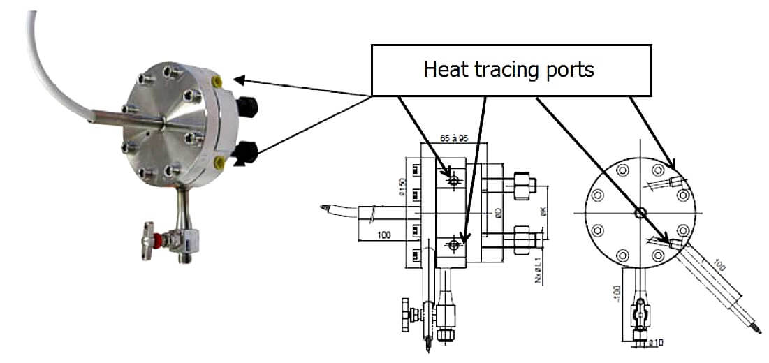
Figure – DP Steam heating facilities
Diaphragm material should be carefully selected according to the fluid properties (e.g. gold plated in presence of hydrogen or subject to hydrogen permeation).
Flange connection should be selected according to the piping/vessel code.
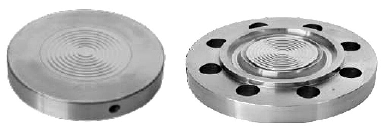
Figure – DP SM or RTJ diaphragm flanges
The inner volume of capillary fluid can affect the measurement accuracy and response time. Capillary with internal 1 mm diameter will minimize the effect of temperature variation but will increase the response time. Capillary with internal 2 mm diameter will decrease the response time but will more affected by the fluid dilatation.
Seal fluids compatibility with the line process fluids should be reviewed to confirm it is suitable and prevent contamination of the process stream (e.g. oxygen service).
In the presence of wax, slurries, clogs flushing rings should be considered. Flushing rings should be fitted with vent and drain facilities. Diaphragm seals should include isolation features to enable maintenance.
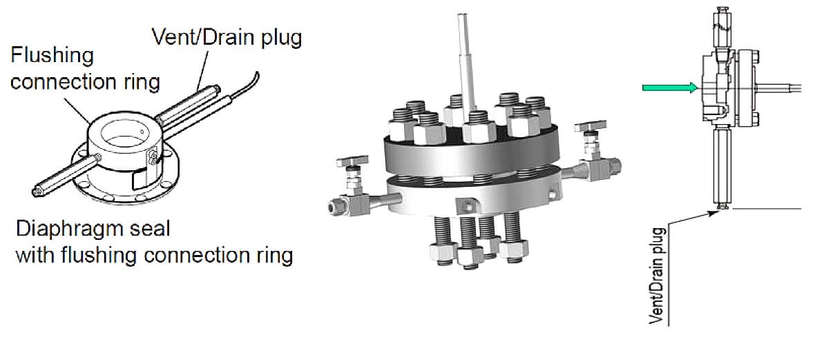
Figure – DP flushing/draining
Installation
Capillary filled seal is sensitive to ambient temperature variation. Protection such as insulation shield, protective cover or installation facing the North should be considered.
Diaphragm seals should have facility to maintain, remove, vent and drain (e.g. isolation features).
The flange fitting should be installed in a vertical orientation. Diaphragm and capillary should be installed in a vertical position.
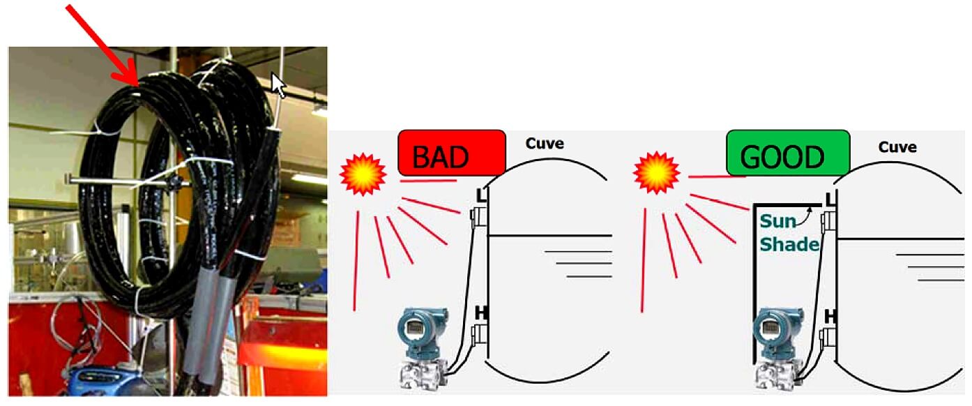
Figure – DP capillary protection
The differential pressure transmitter should be mounted below the lowest level to be measured.
The capillary position should avoid any risks of vaporization.
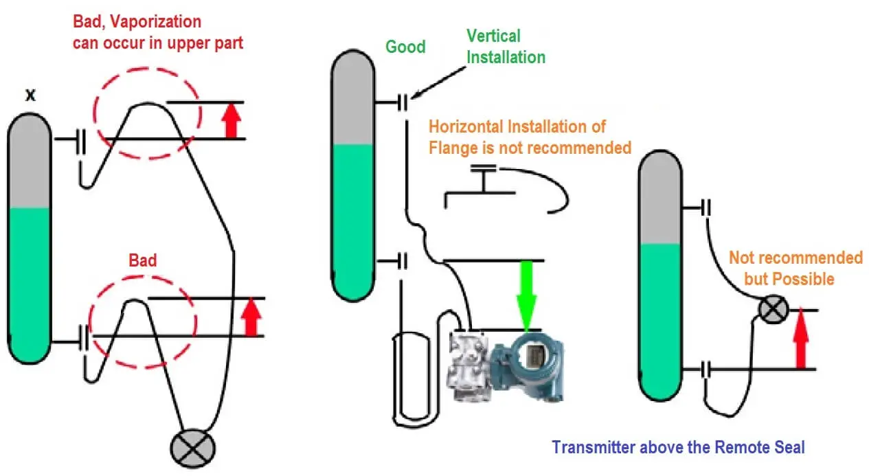
Figure – DP Capillary arrangement
Capillaries should have a minimum radius of curvature of 150 mm, any vibration or friction should be avoided.
Diaphragm seals should be properly handled in the field to avoid damage to diaphragm seal and capillary tubing and potential loss of sensing fill fluid.
Calibration and configuration
Calibration should be performed at Product Manufacturer premises and verified prior to the commissioning activities. Calibration certificate should be provided.
Calibration may be performed in situ using a field pressure calibrator or using a calibrator bench (e.g. for diaphragm seal or specific low pressure).
Getting started, zero adjustment, scale with seals
The oil column height should be taken into account to a zero offset:
- When the tank is empty, the sensor measure the LP weight of the oil column, this value causes a zero offset in the negative, which can be adjusted at the span calibration or during the commissioning by a zeroing with empty vessel.
- Delta scale (or span) by calculation, will normally be adjusted relative to the distance between flanges and to the density of the liquid, then add to the calculated zero value. Or it can be done with full vessel.
- Zero offset can be therefore even more important than the scale itself (especially with the fluorinated oil). We should choose a sensor whose extent of adjustment allows the zero offset.
- For density or multi‐layer measurements, it will be necessary to make the zero by adjustment with 100% of the lightest liquid, full scale will be calculated with 100% of the heaviest liquid.
Getting started, zero adjustment, scale with impulse line dry leg on low pressure side (LP)
LP side (upper connection), column vented to vessel atmosphere:
- When the tank is empty, the sensor measure zero on both side (HP and LP), then DP (differential pressure) is also zero = 4 mA.
- When the tank is full, measurement is height multiply by density, calibration is done for 100%, In case it is possible to know an intermediate level, calibration could be done for another percentage.
- Most important thing: “This required that liquid should not arrive into the upper connection, or the dry leg will be filled and this will make a offset of the zero”.
- For density or multi‐layer measurements, height should be constant, then using a dry leg is clearly not possible, measurement should be done in a vessel which works with an overflow.
Source : International Association of Oil & Gas Producers
Acknowledgements : IOGP Instrumentation and Automaton Standards Subcommittee (IASSC), BG Group, BP, Endress + Hauser, Emerson, Honeywell, Krohne, Petrobras, PETRONAS Carigali Sdn Bhd, Repsol, Siemens, Statoil, Total, Vega, Yokogawa.
Thanks for this article but i think in case of we have two liquids as per above example liquid -1- & liquid -2- includes Gas as the third type of fluid in the closed tank ,so it is better to use Multi phase Density Meter rather than makes this kind of complexity and the disadvantages of using DP transmitter for measurement of density in terms of Height -Pressure – Specific gravity, why because for a specific application it is important to know exactly the density of liquid -1- and -2- and what about the area called interface or we call it in hydrocarbon products SLOP means here the density is neither for liquid -1- not for liquid -2-
And how we can controls this area so it is better to use the theory of tuning fork principle to measure the density (On Line) this is for single liquid in one closed tank and to use Multi phase density for multi phase liquids despite we will have the interface area or we call it SLOP, also this can be detected by other device, personally i used such application in our pumping station for hydrocarbon products in Iraq and all depots or tank farm Area, we have density on line meter and devise to detect the SLOP product and to avoid any type of contamination between hydrocarbon products carrying on one single line, of course this is via pipe lines and form tanks it is the same idea we can install On line density meter using the principle of tuning fork if we have single liquid and if we have more multi phase density meter is the best solution and i think DP transmitters are the best solution for level measurement and flow as well using square root criteria for flow.
Dear sir
How to download at mobile
Go to Google Playstore/itunes then search for “Instrumentation Tools”. Download the App.
How many type of DP transmitter
very very good
hello , i’m Dhruv from india and i want to ask you that we facing the problem which we have installed dp type leval transmitter in tower at bottom side also top side for higher and lower density material but the level was not proper shows on dcs so can you please tell me for this solution and also provide the formula for LRV & URV . and Yaaa we are measuring the interface level transmitter.
What is the reason for using block and bleed valve as well as double block and bleed valve? Is there a governor for this issue? What are the disadvantages of using an isolation without bleeding?
hi
Please help me.
I asked a question two days ago. Is there a standard for using valve block and bleeding in pressure difference measuring devices? In our refinery complex, a single valve has been used. In all pressure measuring devices, and especially in surface measuring devices, there is no possibility of calibration during normal operation.
hello,
please i will like to know the best procedure for isolating/ lining up a capilliary dp transmitter.
and why is my capilliary dp transmitter showing Pv limit and going on high negative value