Measurement principle
The principle of displacement level measurement is based on Archimedes Principle.
Displacement instruments determine liquid level by sensing the buoyant force exerted on a displacer by the liquid it displaces.
Unlike floats, in float‐type level instruments, the displacer moves very little relative to the rising or falling liquid.
Interface liquid–liquid level calculation example
The apparent Force (Fa) = Buoyancy weight (F) – Archimedes force (Pa) …See Below Figure
The apparent mass is Fa/g = Ma = m – ρ1 x S x H – S x hinterface x [ ρ2 – ρ1 ] (Equation [1])
The range is:
- At hinterface = 0 then Ma = m – ρ1 x S x H
- At hinterface = H then Ma = m – ρ2 x S x H
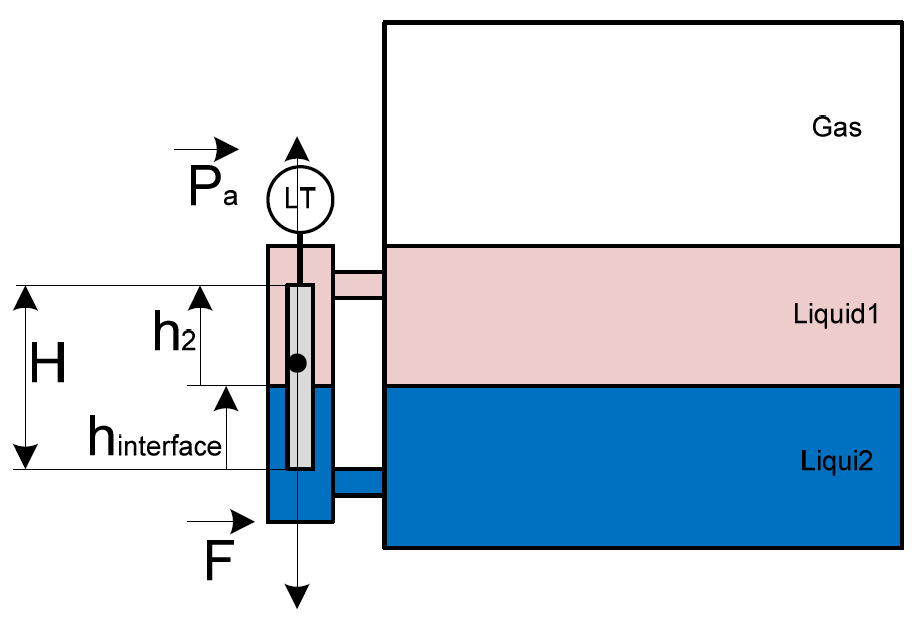
Figure – Displacement Measurement
ρ1 : Liquid1 Density (kg/m3)
ρ2 : Liquid2 Density (kg/m3)
hinterface : Interface Level between the Liquid 1 and Liquid 2 (m)
g: 9.81 (m/s²)
S: Displacer section (m²)
H: Displacer length (m)
Interface measurement requires its own connection into the upper and the lower phase. Equation [1] is applicable if there is only one variable.
For an interface level measurement, there should be an interface. Equation [1] can be used to measure the density of one fluid. In this case, the displacer is fully immersed in the fluid.
Limitations
The level reading from the displacer can be incorrect if the temperature and/or density of the liquid in the vessel is different from that of the liquid in the external cage.
Unreliable measurements are due to dirty, foaming, fouling service as well as turbulent fluid or presence of solid particles in the fluid (e.g. sand).
Vibration (e.g. false alarm) and corrosion affect the level measurement.
Displacers can measure only the range of the displacer length. If the level rises above the top of the displacer, the displacer cannot measure the level.
Displacement transmitters can have higher maintenance needs. Many faults are due to encrustation, freezing of the torque tube, displacer hanger broken or detached, failure of electronic detector angular motion, displacer stuck, and displacer mass change due to corrosion.
Additional features may be required to eliminate turbulent liquid effects on the displacer.
Displacement transmitters can be much more difficult to calibrate, particularly if used for interface measurement.
Removal of the displacer from a vessel may require special rigging.
Displacers are available in a few standard lengths, e.g. 0.36 m to 0.81 m lengths being most common.
Selection
Displacement transmitters can be used in a wide range of temperatures and pressures.
Displacement transmitters should be suitable for interface level measurement if specific gravities differ significantly and the change in specific gravity due to composition or temperature cannot affect the reading.
It is admitted that the difference between specific gravities is greater than 0.1 (if the gravity difference of 0.1 is used, the impact on the accuracy needs to be assessed).
Displacement type level instruments should not be used in severely turbulent, dirty, foaming, fouling service or in case of presence of solid particles in the fluid (e.g. sand). These conditions lead to unreliable measurements from displacement level instruments.
Displacement type level instruments should not be used for liquid‐liquid interfaces where there is potential emulsion forming.
Displacement type level instruments should not be used in liquid‐liquid or liquid–gaseous services where either the upper or lower fluid specific gravity is not relatively constant.
Displacement transmitters can be use also for density measurement if the displacer is permanently and fully immersed in a single fluid.
Design
Displacers should be made of stainless steel or other material compatible with the process fluid.
Displacer should have the height according to the level range for the application.
Installation
The preferred installation for displacers should be a cage/chamber and installed externally to the vessel.
Block, drain and vent valves should be installed to fill and empty the chamber to carry out maintenance activities.
Vessel nozzles should be located with respect to measuring interface level.
Instrument connections directly at the bottom of the vessel should be avoided.
Calibration and configuration
Calibration should be performed at Product Manufacturer premises and verified prior to the commissioning activities.
Calibration may be performed in situ or on a bench calibration with weights. Bench calibration with weights should be performed using the apparent mass.
In situ calibration should be performed using a level gauge or sight glass if fitted. Otherwise, a clear flexible external tube could be used.
Below Figure describes a typical arrangement which should be used to calibrate chamber mounted instruments in-situ.
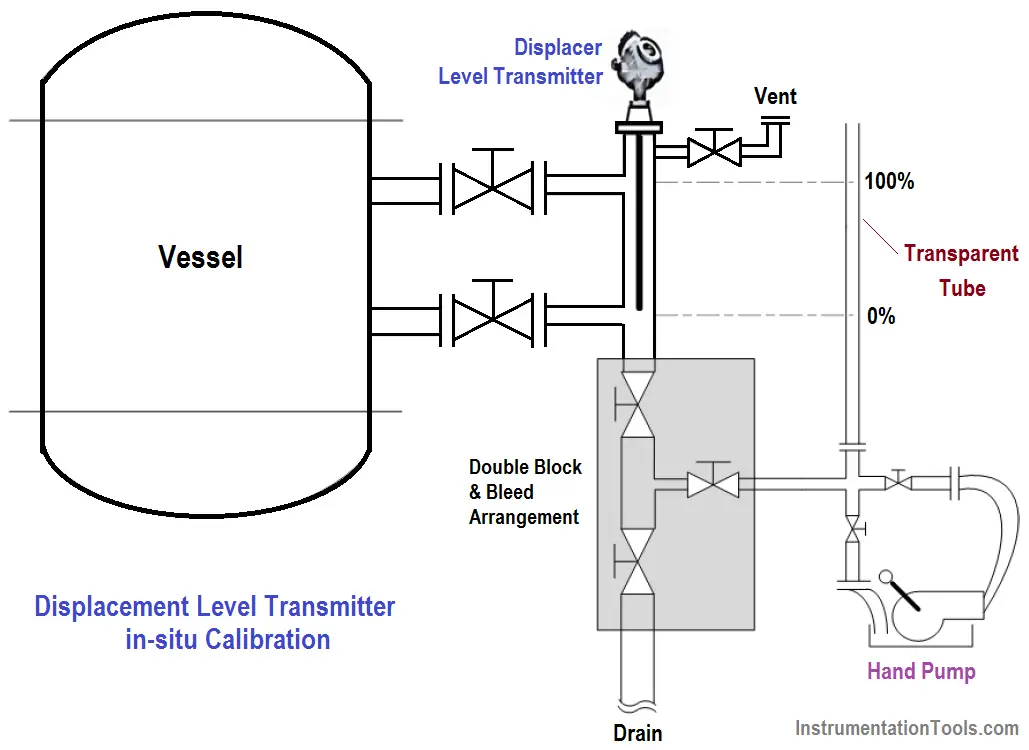
Figure – Displacement in-situ calibration
The displacer level transmitter (or any other buoyancy level transmitter) uses the effect of buoyancy. When the displacer is immersed in the process fluid, this buoyancy effect will make the displacer lighter than the non immersed displacer.
This change of displacer weight is then detected by the sensor (whether use torque tube or LVDT) and then translated as a fluid level.
Before we calibrate the displacer level transmitter, we must aware that the transmitter has been set at factory as per process fluid Specific Gravity (SG), while we will use water as the calibration fluid.
When the displacer is operated by using actual process fluid, it will show 4 mA at low level (the displacer is not immersed) and 20 mA at high level (the displacer is fully immersed).
Thus before we calibrate the transmitter, we need to calculate the equivalence of this buoyancy effect if we use water as the test fluid instead of using actual process fluid (which is in practice are very difficult to get).
Typical tools required for calibration:
- 24 VDC power supply
- Multimeter digital
- Water Supply Connection
- HART communicator
- Screwdriver set
- Wrench set
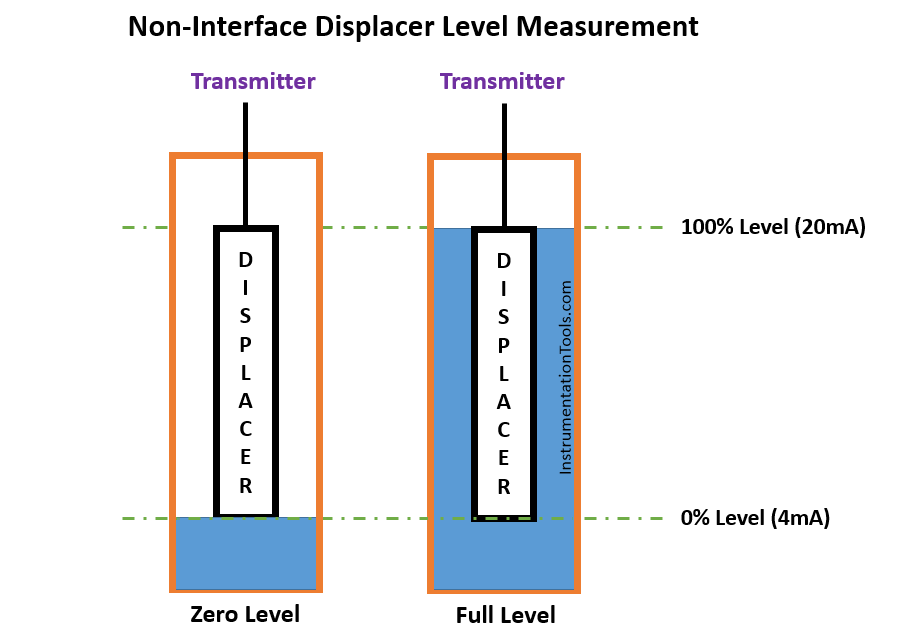
Non-Interface Displacer Level Transmitter Calibration Procedure
1. Calculate the equivalence water level
Zero level = displacer not immersed (no need certain adjustment)
Calculate the high level using this equation:
(Process Fluid Operating SG / Water SG)*Transmitter Level Range
2. Set up the Displacer Level Transmitter to column or temporary support as shown in the calibration setup file below.
3. Fill the level transmitter chamber with water up to the centre of the lower part flange of the LIT cage as a zero level.
4. By using handheld HART communicator set this level as zero level (see also in the LCD display of the transmitter, it should show zero level).
5. Read the mA output of the transmitter by using a multimeter. Adjust (if any) through the HART communicator so that the output of the transmitter (on multimeter) is 4 mA.
6. Fill the level transmitter chamber with water up to the calculated equivalence high level above.
7. By using handheld HART communicator set this level as high level (see also in the LCD display of the transmitter, it should show high level).
8. Read the mA output of the transmitter by using a multimeter. Adjust (if any) through the HART communicator so that the output of the transmitter (on multimeter) is 20 mA.
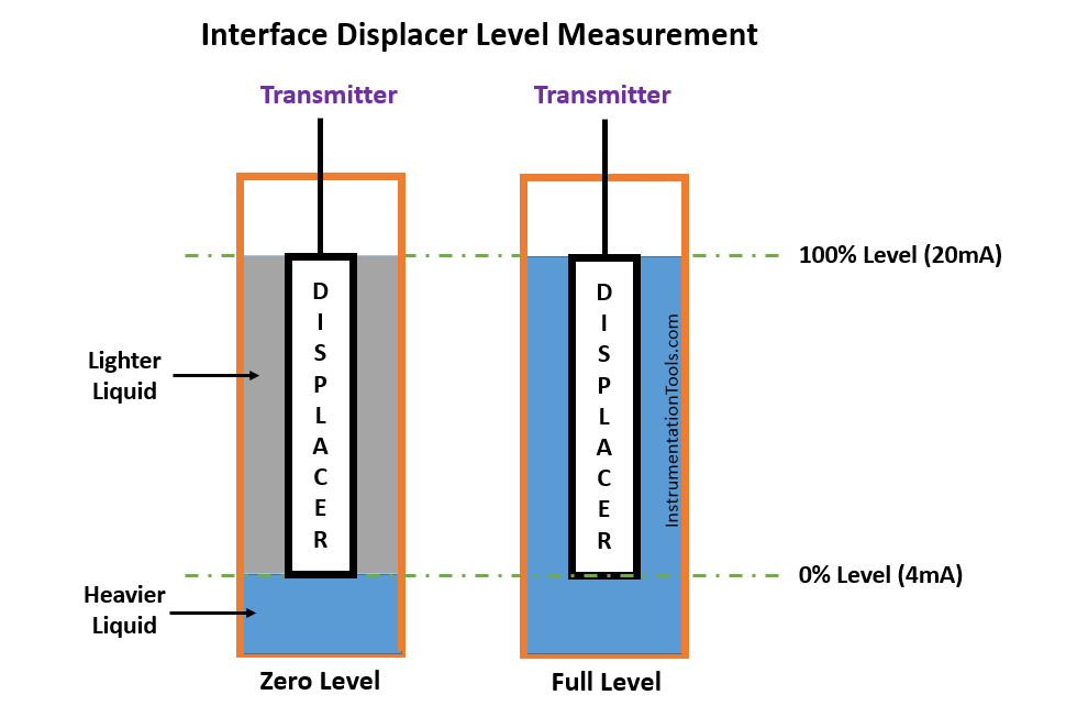
Interface Displacer Level Transmitter Calibration Procedure
1. Calculate the equivalence water level
Calculate zero level using this equation:
(Lighter Process Fluid Operating SG / Water SG)*Transmitter Level Range
Calculate the high level using this equation:
(Heavier Process Fluid Operating SG / Water SG)*Transmitter Level Range
2. Set up the Displacer Level Transmitter to column or temporary support as shown in the calibration setup file below.
3. Fill the level transmitter chamber with water up to the calculated equivalence zero level above.
4. By using handheld HART communicator set this level as zero level (see also in the LCD display of the transmitter, it should show zero level).
5. Read the mA output of the transmitter by using a multimeter. Adjust (if any) through the HART communicator so that the output of the transmitter (on multimeter) is 4 mA.
6. Fill the level transmitter chamber with water up to the calculated equivalence high level above.
7. By using handheld HART communicator set this level as high level (see also in the LCD display of the transmitter, it should show high level).
8. Read the mA output of the transmitter by using a multimeter. Adjust (if any) through the HART communicator so that the output of the transmitter (on multimeter) is 20 mA.
Example of equivalence water level calculation:
Level Transmitter Level Range = 38 inch
Water SG = 1
Process Fluid SG = 0.84
Equivalence high level using water = (0.84/1)*38 = 31.92 inch
It means the displacer should show 20 mA while we fill the chamber up to 31.92 inch with water fluid as test fluid.
Example of Interface Application
Level Transmitter Level Range = 38 inch
Water SG = 1
Lighter Process Fluid SG = 0.695
Heavier Process Fluid SG = 0.994
Equivalence zero level using water = (0.695/1)*38 = 26.41 inch
It means the displacer should show 4 mA while we fill the chamber up to 26.41 inch with water fluid as test fluid.
Equivalence high level using water = (0.994/1)*38 = 37.772 inch
It means the displacer should show 20 mA while we fill the chamber up to 37.772 inch with water fluid as test fluid.
Note: This typical maintenance procedure is just an illustration of how to regularly service a displacer level transmitter for academic purpose only. This typical procedure shall not be used as day to day operation guidance. The vendor specific maintenance manual shall be used in detail.
Source : International Association of Oil & Gas Producers
Acknowledgements : IOGP Instrumentation and Automaton Standards Subcommittee (IASSC), BG Group, BP, Endress + Hauser, Emerson, Honeywell, Krohne, Petrobras, PETRONAS Carigali Sdn Bhd, Repsol, Siemens, Statoil, Total, Vega, Yokogawa.
great work, explanation of the transmitter is very elaborate. I have one doubt, does the pressure and temperature of vessel affects the transmitter reading. I have Foxboro 144LD installed in my plant for propylene service and the pressure is around 20Kg/cm2 and temp. is -20DegC, please suggest what density should i use for propylene
valuable information about level transmitters calibration, but graphic is not seen.
Thank you sir it was very helpful
But I have one question and I hope that I can get the answer
_ what do you mean by Transmitter level rang (it confused me when you mentioned this parameter with inches)