In Control Valve Sequencing, for example, both control valves received the same pneumatic signal from a common I/P (current-to-pressure) converter.
This means each valve received the exact same pressure signal from the transducer for any given controller output value. Sequencing of the two valves (i.e. making each one respond differently to the same air pressure signal), therefore, was a matter of setting each valve to a different bench-set pressure range.
It should be understood, however, that setting up two control valves with different bench-set ranges is not the only way to split-range a pair of valves. Other ways exist as well, each with its own advantages and disadvantages.
Control Valve Sequence Methods
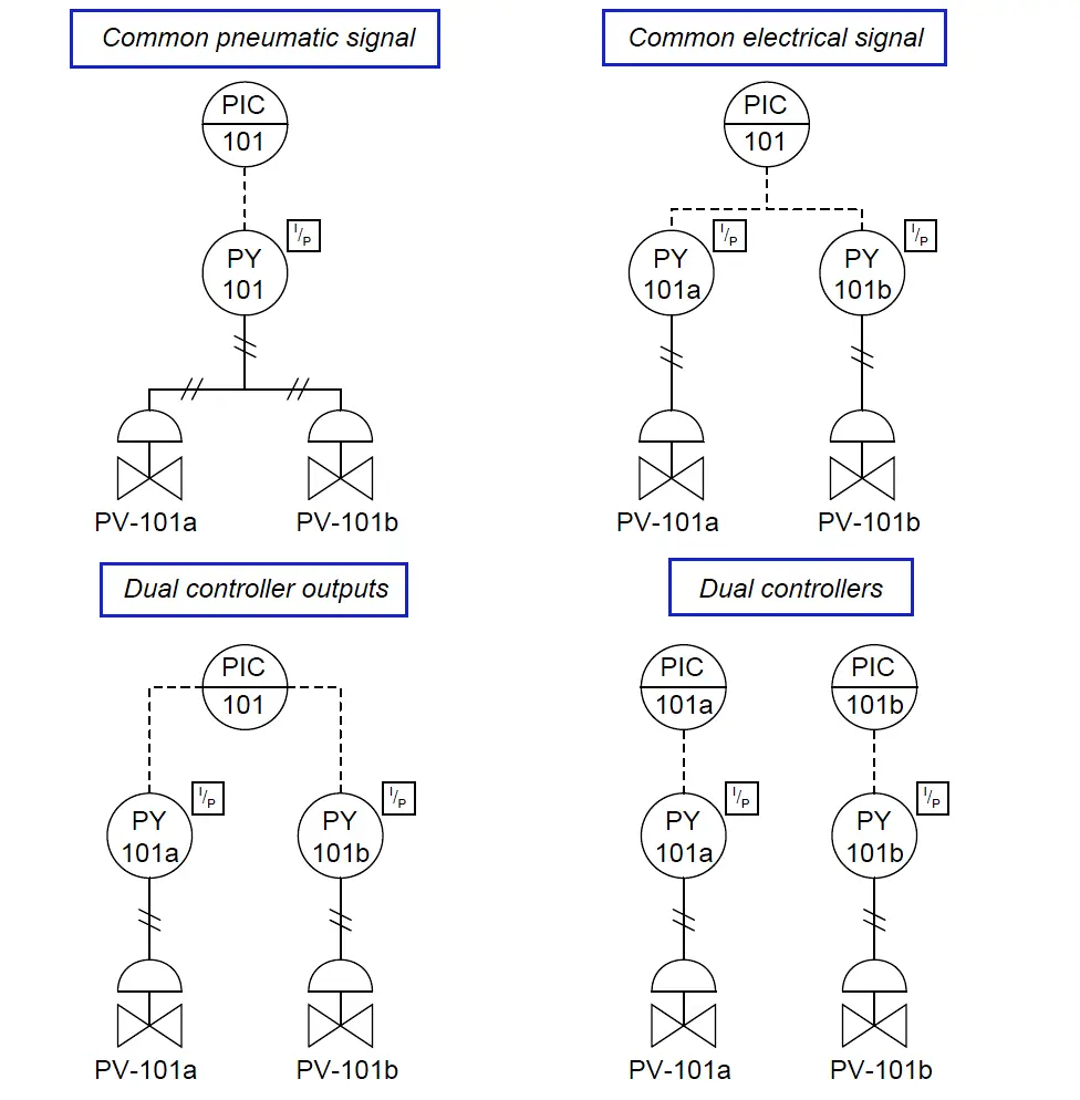
The following illustrations depict several alternative methods for control valve sequencing (split-ranging):

The common pneumatic signal approach (one controller, one I/P transducer) is simple but suffers from the disadvantage of slow response, since one I/P transducer must drive two pneumatic actuators.
Response time may be improved by adding a pneumatic volume booster between the I/P and the valve actuators, or by adding a positioner to at least one of the valves.
Either of these solutions works by the same principle: reducing the air volume demand on the one common I/P transducer. Wiring two I/P transducers in series so they share a common signal current is another way to split-range two control valves.
This approach does not suffer from slow response, since each valve has its own dedicated I/P transducer to supply it with actuating air. We now have a choice where we implement the split ranges:
we can do it in the I/P transducers (i.e. each I/P transducer having a different calibration) or in the control valves (i.e. each control valve having a different bench set pressure range).
Since it is generally easier to re-range an I/P than it is to rebuild a control valve with a different spring (to give it a different actuating pressure range), this approach has the advantage of convenient configuration.
A disadvantage of the series-wired I/P strategy is the extra burden placed on the controller’s output signal circuitry: one must be careful to ensure the two series-connected I/P converters do not drop too much voltage at full current, or else the controller may have difficulty driving both devices in series.
Another (potential) disadvantage of series-connected valve devices in one current loop is the inability to install “smart” instruments communicating with the HART protocol, since multiple devices on the same loop will experience address conflicts (Note 1). HART devices can only work in hybrid analog/digital mode when there is one device per 4-20 mA circuit.
Note 1 : Although the HART standard does support “multidrop” mode where multiple devices exist on the same current loop, this mode is digital-only with no analog signal support.
Not only do many host systems not support HART multidrop mode, but the relatively slow data communication rate of HART makes this choice unwise for most process control applications. If analog control of multiple HART valve positioner devices from the same 4-20 mA signal is desired, the address conflict problem may be resolved through the use of one or more isolator devices, allowing all devices to share the same analog current signal but isolating each other from HART signals.
A popular way to implement split-ranging is to use multiple 4-20 mA outputs on the same controller. This is very easy to do if the controller is part of a large system (e.g. a DCS or a PLC) with multiple analog output channels. If multiple outputs are configured on one controller, each valve will have its own dedicated wire pair for control.
This tends to result in simpler wiring than series-wired I/P transducers or positioners, since each valve loop is a standard 4-20 mA circuit just like any other (non-split-ranged) control valve loop circuit. It may also be the most practical way to implement split-ranging when “smart” valve positioners are used, since the dedicated loop circuits allow for normal operation of the HART protocol with no address conflicts.
An advantage of dual controller outputs is the ability to perform the split-range sequencing within the controller itself, which is often easier than re-ranging an I/P or calibrating a valve positioner.
This way, the 4-20 mA signals going to each valve will be unique for any given controller output value. If sequenced as such, the I/P transducer calibration and valve bench-set values may be standard rather than customized.
Of course, just because the controller is capable of performing the necessary sequencing doesn’t mean the sequencing must be done within the controller. It is possible to program the controller’s dual analog outputs to send the exact same current signal to each valve, configuring each valve (or each positioner, or each I/P transducer) to respond differently to the identical current signals.
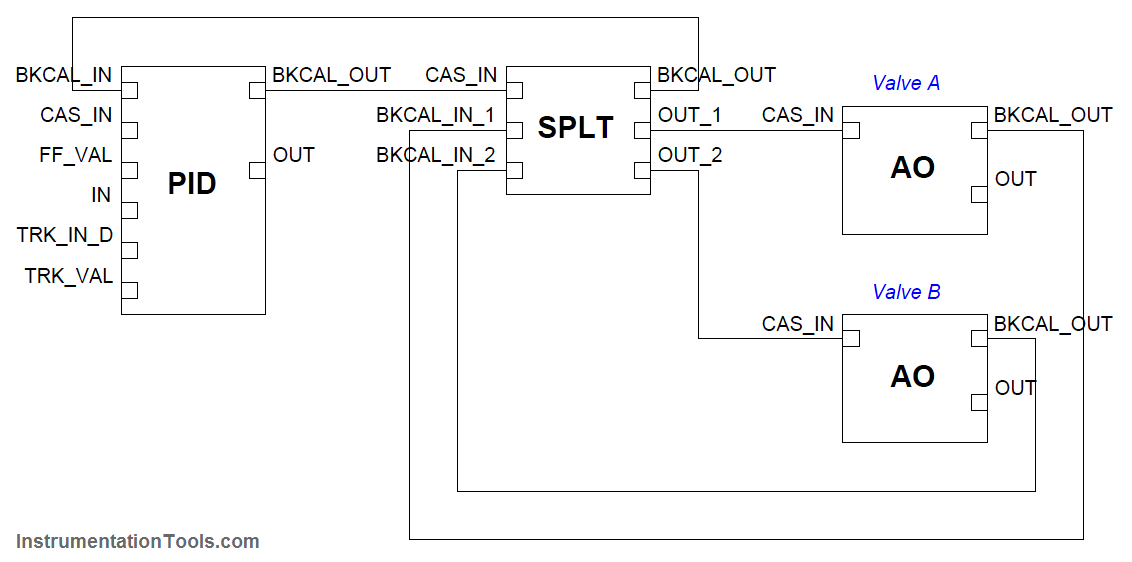
A digital adaptation of the dual-output controller sequencing method is seen in FOUNDATION Fieldbus systems (Note2), where a special software function block called “SPLT” exists to provide splitranged sequencing to two valves. The “SPLT” function block takes in a single control signal and outputs two signals, one output signal for each valve in a split-ranged pair.
Note 2 : To review, Fieldbus is an all-digital industrial control protocol, where instruments connect to a control system and to each other by means of a single network cable. Signals are routed not by specific wire connections, but rather by software entities called function blocks whereby the engineer or technician programs the instruments and control system what to do with those signals.
The function blocks shown in this example would typically be accessed through the graphic display of a DCS in a real Fieldbus system, lines drawn between the blocks instructing the system where each of the instrument signals need to go.
The function block diagram for such a system appears here:

In this Fieldbus system, a single PID control block outputs a signal to the SPLT block, which is programmed to drive two unique positioning signals to the two valves’ AO (analog output) blocks.
It should be noted that while each AO block is unique to its own control valve, the SPLT and even PID blocks may be located in any capable device within the Fieldbus network.
With FOUNDATION Fieldbus, control system functions are not necessarily relegated to separate devices. It is possible, for example, to have a control valve equipped with a Fieldbus positioner actually perform its own PID control calculations and split-ranged sequencing by locating those function blocks in that one physical device!
Dual controllers are an option only for specialized applications requiring different degrees of responsiveness for each valve, usually for exclusive or progressive split-ranging applications only.
Care must be taken to ensure the controllers’ output signals do not wander outside of their intended ranges, or that the controllers do not begin to “fight” each other in trying to control the same process variable (Note3).
Note 3 : Both controllers should be equipped with provisions for reset windup control (or have no integral action at all), such that the output signal values are predictable enough that they behave as a synchronized pair rather than as two separate controllers.
An important consideration – and one that is easily overlooked – in split-range valve systems is fail-safe mode. The basis of fail-safe control system design is that the control valve(s) must be chosen to fail in the mode that is safest for the process in the event of actuating power loss or control signal loss.
The actions of all other instruments in the loop should then be selected to complement the valves’ natural operating mode.
In control systems where valves are split-ranged in either complementary or exclusive fashion, one control valve will be fully closed and the other will be fully open at each extreme end of the signal range (e.g. at 4 mA and at 20 mA).
If the sequencing for a set of complementary or exclusive split-ranged control valves happens after the controller (e.g. different actuator actions) the valves must fail in opposite modes upon loss of controller signal.
However, if it is deemed safer for the process to have the two valves fail in the same state – for example, to both fail closed in the event of air pressure or signal loss – we may use dual sequenced controller outputs, achieving either complementary or exclusive control action by driving the two valves with two different output signals.
In other words, split-ranging two control valves so they normally behave in opposite fashion does not necessarily mean the two valves must fail in opposite states. The secret to achieving proper failure mode and proper split-range sequencing is to carefully locate where the sequencing takes place in the control system.
Types of Control Valve Sequences
-
Complementary Control Valve Sequence
-
Exclusive Control Valve Sequence
-
Progressive Control Valve Sequence