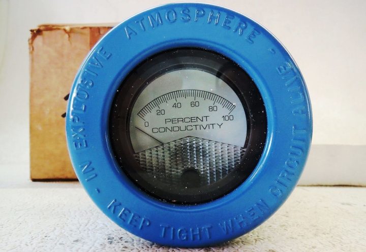
In this article, we discuss about How calibration is to be performed through decade resistance box for a conductivity transmitter.

Image courtesy : Emerson analytical
Theory :
Conductivity is the ability of any solution to pass a electric current. In any liquid current is carried by cation and anions.
Conductivity of any solution is depending on following factors:
- Concentration
- Mobility of ions
- Valence of ions
- Temperature
The unit of conductivity is micro-Siemens per centimeter or µS/cm.
Need of conductivity measurement:
- To detect the leak in a process vessel: Water used for cooling in heat exchangers and surface condensers for temperature control. If any Leakage occurred in vessel tube which mix the cooling water into the process liquid and can result in potentially harmful contamination. Its can detect by conductivity measurement
- Conductivity is used to monitor the buildup of dissolved ionic solids in evaporative cooling water systems and in boilers.
- Water treatment facilities
Calibration of Conductivity Transmitter :
Calibration can be done by two methods.
- With standard sample
- With resistance decade box
Here we are discussing calibration with resistance decade box.
And consider Emerson make conductivity analyser or transmitter and model number is 1181T.
Formula to find out the resistance :
As we are discussing about calibration via a decade resistance box, we need to calculate the equivalent resistance which to be applied from a decade resistance box to the conductivity transmitter for the calibration purpose. As per our process temperature range, we have three different types of formulas for the resistance calculations.
The three formulas as per process temperature range are :
- If your sample temperature is in between 5 to 85 deg C
Resistance (conductivity) = Probe Constant X 1,000,000 / F.S. Conductivity
- If your sample temperature is in between 50 to 150 deg C
Resistance (conductivity) = 0.4 X Probe Constant X 1,000,000 / F.S. Conductivity
- If your sample temperature is in between 100 to 200 deg C
Resistance (conductivity) = 0.4 X Probe Constant X 1,000,000 / F.S. Conductivity
In our discussions, we considered sample temperature is in between 0 – 50 deg Celsius. so first formula is applied in our below example.
Calibration Example :
Suppose a conductivity transmitter calibration to be carried out which has range 0 – 100 µS/cm and cell constants 0.1
Solution:
For any transmitter, there are two minimum calibration checks will be there.
They are
- Zero Calibration : For verifying the zero reading of the transmitter
- Span Calibration : For verifying the calibrated range of the transmitter
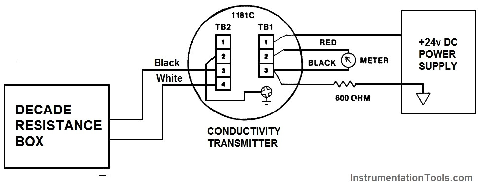
Connect the decade box and power supply as shown in below figure.

Zero calibration :
For Zero calibration : remove/disconnect the decade resistance box and adjust the transmitter to 4 ma for Zero reading.
Span calibration :
- First calculate the required resistance for the span calibration.
Resistance (conductivity) = Probe Constant X 1,000,000 / F.S. Conductivity
= 0.1 X 1,000, 000 / 100 ohm = 1000 ohm = 1 kilo ohm
- Connect Decade resistance box to the transmitter
- Adjust the resistance to 1 kilo ohms (as calculated above).
- Check the current output of transmitter & it has to show 20mA otherwise adjust.
Middle point calibration :
we can also do a intermediate calibration check of the 4-20mA transmitter range.
Here we considered 12mA for the calibration purpose.
So again calculate the resistance for the middle point calibration
Resistance = 2 X full scale resistance conductivity
= 2 X 1000 ohm = 2 kilo ohm
- Connect Decade resistance box to the transmitter
- Adjust the resistance to 2 kilo ohms (as calculated above).
- Check the current output of transmitter & it has to show 12 ma ( ±0.16mA ) otherwise adjust.
Reference : Emerson analytical
This described method is not correct.
First of all it is assumed that the sample (process) temperature dependency alva is linear in particular temperature ranges. This may be acceptable valid for most of the water applications but certainly not for many other processes !
Then the cell constant K is also not explained how to choose the correct K value based on the measuring range of conductivity!
A far better full explanation is given by Yogogawa, who took it from earlier Electrofact.
Any comment, please contact me.
Mostly we measure the conductivity of water which is used in heat exchanger and in this article describe how to calibrate so k value is already given with sensor and transmitter
Which formula to be used if sample temp is in between 50 to 80 degree celcius?
which method is used to calibrate the toroidal conductivity analyzer?
Option A) with probe discounted ,connect decade resistance box across the input terminal , then dial a desire resistance.
B) with probe disconnected loop a wire toroidal , attached decade resistance box, then in desire resistance