Failure rate tends to be constant during a component’s useful lifespan where the major cause of failure is random events (“Acts of God”). However, lambda does not remain constant over the entire life of the component or system.
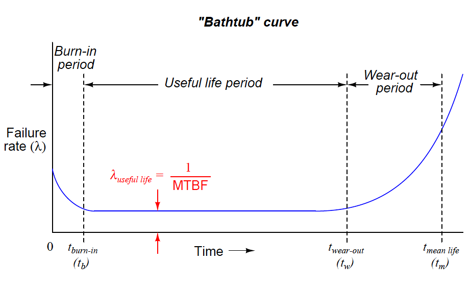
A common graphical expression of failure rate is the so-called bathtub curve showing the typical failure rate profile over time from initial manufacture (brand-new) to wear-out:
Bathtub Curve

Bathtub Curve profiles the failure rate of a large sample of components (or a large sample of systems) as they age. Failure rate begins at a relatively high value starting at time zero due to defects in manufacture.
Failure rate drops off rapidly during a period of time called the burn-in period where defective components experience an early death. After the burn-in period, failure rate remains relatively constant over the useful life of the components, and this is where we typically define and apply the failure rate (λ).
Any failures occurring during this “useful life” period are due to random mishaps (“Acts of God”). Toward the end of the components’ working lives when the components enter the wear-out period, failure rate begins to rise until all components eventually fail.
The mean (average) life of a component ™ is the time required for one-half of the components surviving up until the wear-out time (tw) to fail, the other half failing after the mean life time.
Several important features are evident in this “bathtub” curve. First, component reliability is greatest between the times of burn-in and wear-out.
For this reason, many manufacturers of high-reliability components and systems perform their own burn-in testing prior to sale, so that the customers are purchasing products that have already passed the burn-in phase of their lives.
To express this using colloquial terms, we may think of “burnt-in” components as those having already passed through their “growing pains,” and are now “mature” enough to face demanding applications.
Another important measure of reliability is the mean life. This is an expression of a component’s (or system’s) operating lifespan. At first this may sound synonymous with MTBF, but it is not. MTBF – and by extension lambda.
since MTBF is the reciprocal of failure rate – is an expression of susceptibility to random (“chance”) failures. Both MTBF and λuseful are quite independent of mean life. In practice, values for MTBF often greatly exceed values for mean life.
To cite a practical example, the Rosemount model 3051C differential pressure transmitter has a suggested useful lifetime of 50 years (based on the expected service life of tantalum electrolytic capacitors used in its circuitry), while its demonstrated MTBF is 136 years.
The larger value of 136 years is a projection based on the failure rate of large samples of these transmitters when they are all “young,” which is why one should never confuse MTBF for service life. In reality, components within the instrument will begin to suffer accelerated failure rates as they reach their end of useful lifetime, as the instrument approaches the right-hand end of the “bathtub” curve.
When determining the length of time any component should be allowed to function in a high reliability system, the mean life (or even better, the wear-out time) should be used as a guide, not the MTBF. This is not to suggest the MTBF is a useless figure – far from it.
MTBF simply serves a different purpose, and that is to predict the rate of random failures during the useful life span of a large number of components or systems, whereas mean life predicts the service life period where the component’s failure rate remains relatively constant.