In this article, we will discuss about the turbine flow meters troubleshooting tips and corrective action.
Turbine Flow Meters
What is a turbine flow meter? How and when is it used?
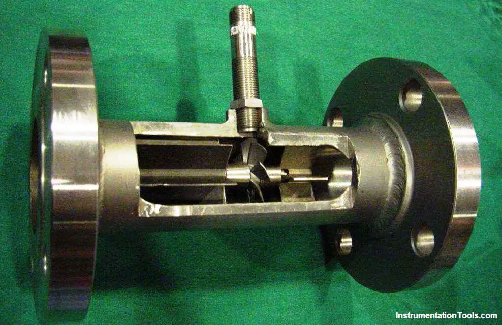
A turbine flow meter is a liquid/gas velocity measurement device.
The turbine flow meter contains a free-spinning turbine rotor that turns at a speed that is proportional to the flow velocity.
Can liquid meters measure gas and vice versa?
No – gas in a liquid meter will cause the meter to read high and can cause catastrophic failures.
Liquid going through a gas meter will cause erroneous indications of the gas flow rate and can cause meter damage.

How do you size gas turbines?
With gas turbines, flowing pressure and temperature are taken into account, as well as the flow rate.
What is the maximum working pressure?
The maximum working pressure of meters is determined by the end connections.
What size meter will I need for a certain size pipe?
Meter size depends on the flow rate being metered, not pipe size. Most oilfield applications oversize the pipe so the meter flow rate size may be smaller than the pipe size.
If the fluid being measured is a non-lubricating liquid, such as solvent, gasoline, acetone, alcohol, etc., the meter must be run in the upper 60% of the operating range.
Also Read: Foundation Fieldbus Transmitter Calibration
What happens when the flow goes in the reverse direction in the meter?
The meter is not damaged as the meters are designed to be Bi-Directional, but the counter will read the total of the forward flow and the reverse flow.
For example, if five barrels flow through the meter in the forward direction, and then four barrels flow back through the meter in the reverse direction, the counter will show nine barrels even though the net transfer through the meter is only one barrel.
How do you size meters for certain applications?
Injection wells – flow rates, working pressure, and end connections.
Separators – recommend snap dumps. (You need the instantaneous flow rate when it is dumping, not the total amount dumped per day.)
Oil meters – consider the viscosity of oil and gas in the fluid. Install a back-pressure device downstream of the meter that will keep the gas entrained in the fluid.
Meters in general – try to mid-range if possible.
Meters for CO2 service – recommend upper 60% range. Measure it in the liquid state only
What happens to accuracy when you are above or below the range of the meter?
The bottom end of the flow range is the critical point. Below this minimum, the factor changes with the flow rate change. Each meter performs differently, so it is not possible to predict the performance. The top end of the flow range is based more on bearing wear than accuracy.
The meter will still be accurate above the top end of the range, but the kit will not last long if continuously runs above the top end of the flow range. Over-range use should be limited to 10% of the maximum flow rate and not more than 10% of the time.
What is the difference between the dump rate and the production rate?
Production rate: how much the well makes in a day Dump rate: the instantaneous flow rate.
What is the life expectancy of the meter?
Many factors can affect this, but, normally, if debris is kept out of the meter and fine particles such as sand are kept to a minimum, the meter can last for many years.
Life expectancy depends entirely on the application and meter size.
Is the turbine meter easy to work on and maintain?
Yes – minimal tools are required
Also Read: Turbine Flow Meter Verification
How long will the rotor and vane of the meter last?
The longevity of the rotor and vane kit depends strictly on the application. A meter that measures a clean lubricating fluid will last longer than one that measures a dirty, sandy, non-lubricating product.
The life of the meter depends on the application and meter size.
Can the meter be used with propane, butane, CO2, etc.?
Yes – the product must be liquid, and because it is less lubricating, it is best used in the upper 60% range of the meter.
Precautions must be exercised to prevent gas flashing, which can cause catastrophic failures and/or high readings.
Can meters be used with piston-type pumps?
The turbine meter works well in this application compared to other measurement devices. However, due to the constant pulsation of the fluid, the meter may be the best choice because of its design.
Depending on the back pressure and the proximity of the installed meter to the pump, the snap rings can wear, and the loss of one vane and the rotor can occur. If the turbine meter is some distance away from the triplex pump, the standard meter will most likely give adequate performance.
What is a calibration factor and how is a meter calibrated? What happens if the calibration factor tag is lost?
The calibration factor is the number of pulses per gallon a meter will produce. Every meter is individually calibrated by flowing a known volume of water through the meter at five different flow rates – one at the maximum rate, one at the minimum rate, and three at rates equidistantly spaced between. This calibration factor is put on a plastic tag and attached to the conduit pickup adapter of a meter.
Since kits are also calibrated individually and come with their own calibration factor, if the original kit has been changed and the new calibration factor tag is lost, the only way to get the actual factor is to send the meter to the vendor for re-calibration or a third party proving facility. Sometimes a nominal factor will be close enough for the application.
If a meter requires repairs, it is critical to change the entire kit. Never replace or interchange parts.
What method is used to calibrate turbine flow meters and replacement rotor and vane kits?
The volumetric tank method is used. The volume of the calibration tanks is determined by filling them with water that is measured by tanks that are calibrated and certified by the National Institute of Standards and Technology.
These calibration tank volumes are checked periodically. Each flow meter and kit is placed in a flowline, and the calibration tank is filled at five different flow rates over the range of the meter. One run is performed at the maximum rate, one at the minimum rate, and three runs are performed at rates equidistantly spaced between the maximum and minimum rates.
The total number of pulses generated by the flow meter at each flow rate is recorded. The total pulses are divided by the total volume at each flow rate to determine the calibration factor. The mean factor is determined as halfway between the high and low factors.
The flow meter is tagged with the mean factor. The maximum deviation between the mean factor and high or low factor cannot exceed ± 0.5% for industrial grade meters or ± 1.0% for standard grade meters.
What is the most common problem with the meters?
Debris getting in the meter can cause readings to be high, low, or non-existent. This problem can be solved with the use of a strainer or filter ahead of the meter.
These are recommended in all meter installations where debris or particles may be present in the flow stream.
What if the meter is not reading?
Check for debris that prevents the turbine from turning or a bad pickup.
The meter reads low, and there is no debris in it.
Check for debris binding the turbine. Remove the meter internals to thoroughly observe, because some debris, such as Teflon tape, cannot be seen by just looking through the meter.
Check for damage to the rotor or shaft, bearing wear, and external factors actually reducing flow such as a valve, a well pressuring up due to a blockage, an incorrect divisor, a malfunctioning totalizer, or a shaft broken on one side of the rotor.
Debris can cause one of three problems:
- No reading at all (the turbine is not turning)
- Low reading (debris is binding the turbine)
- High reading (debris is jetting fluid through the turbine)
The rate seems to be increasing, but the pressure does not change.
Check for a buildup in the meter and upstream piping, such as scale, paraffin, etc.
Also Read: Flow Nozzle Principle
What causes turbine flow meters to read high, more than the actual flow?
- Debris blocking part of the inlet to the meter
- A partially closed valve or other restriction upstream of the meter
- An elbow, tee, or some other flow diverter too close to the upstream end of the meter viscosity of the fluid being measured
- Misalignment of the meter or gaskets in the flow line
- Wax or scale buildup in the pipe or meter
- An incorrect divisor
- A malfunctioning totalizer.
- A malfunctioning/faulty magnetic pickup.
- Noise from vibration or nearby energy source emitting noise.
The meter has suddenly started reading very high.
Check for debris lodged on the upstream end of the turbine or a change of fluid conditions that could cause a gas breakout. Gas or air in the fluid can cause also high readings. A valve used for rate control must be mounted on the downstream side of the meter.
Backflow is measured and added to the regular flow volume, causing the totalizer to yield excessively high values. A leaking check valve, therefore, can cause a high totalizer reading.
What problems will make a liquid meter read inaccurately?
Debris in the meter, a broken shaft, viscous fluids, gas in the flow line, and/or improper sizing or installation can cause inaccurate readings.
When should a rotor and vane kit be replaced due to bearing wear?
Bearing wear on a shaft will appear as a dimple at the end of the shaft or a groove cut around the shaft ends. When a groove is observed, the kit should be replaced.
As a rule of thumb, if a dimple covers 66% of the surface area of the end of the shaft, the kit should be replaced. If the groove on the side of the shaft can be felt, it should be replaced.
How do you check pickups?
The pickup can be checked with an ohmmeter, or it can be connected to a properly working readout device.
When a wire brush or screwdriver is passed across the pickup tip, the readout should show a rate or update of the total if the pickup is functioning properly
If you liked this article, then please subscribe to our YouTube Channel for Instrumentation, Electrical, PLC, and SCADA video tutorials.
You can also follow us on Facebook and Twitter to receive daily updates.
Read Next:
- Coriolis Mass Flow Meter
- Flow Meter Interview Questions
- What is Square Root Extractor?
- Orifice Plate Flow Requirements
- Flow Meter Calibration Procedure