What is a Thermowell Wake Frequency Calculation?
A Wake Frequency Calculation is used to determine or prove the required dimensions and suitability of a Thermowell based on the process conditions. The fluid will form a wake, known as a “Von Karman Trail”.
The wake has a specific frequency, which is a function of the diameter of the thermowell and the fluid velocity. If the wake frequency coincides with the natural frequency of the thermowell, the well will vibrate and it leads to destruction.
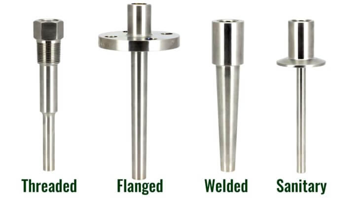
ThermoWells
Thermowells are principally used with Thermocouples, RTDs (Resistance Temperature Detectors) and Bimetal Thermometers in applications where it is necessary to measure temperature at high pressure (above 75 psig) or in hostile environments.
They are also used for isolation, so a sensor can be replaced without having to shut down the process. Thermowells are machined from solid barstock.
Safe working pressures depend on the well material, operating temperature and the velocity of the flowing medium.
Thermowell Vibration
When fluid flows past a thermowell, the change in fluid momentum creates a turbulent wake behind the well.
Vortices form in this wake, and shed from alternate sides of the well. The vortex shedding frequency (or Wake frequency) is linear with flow velocity and inversely proportional to thermowell tip diameter.
These shedding vortices impose on the thermowell, a periodic force comprising two components – (i) a lift force, normal to direction of flow, oscillating at the wake frequency, and (ii) a smaller drag force, parallel to flow, oscillating at twice the wake frequency.
These vortex-induced forces, which cause thermowell vibration, are normally small with the magnitude of the vibrations generally negligible.
However, as the wake frequency (fw) approaches the natural frequency (fn) of the thermowell (within 20%), it can shift and lock-in to the natural frequency.
When fw = fn, the thermowell goes into resonance, and vibrating forces increase rapidly. The resultant vibrations can cause mechanical failure of the well.
The Murdock calculations (and companion ASME PTC 19.3) consider only the oscillating lift force as the cause of thermowell vibration. The ratio of wake to natural frequency is restricted to a maximum of 0.8 to eliminate the possibility of resonance.
Although the oscillating drag force is small, it can force the thermowell into resonance at lower velocities because it occurs at twice the wake frequency.
For high-density fluids (liquids and high pressure steam), the Murdock analysis is not adequate. When the oscillating drag component is included, the velocity rating can be reduced by up to 50%.
The calculations included herein are modified to include in-line resonance due to the oscillating drag force, correction for the magnification ratio and use of the actual natural frequency of the well rather than the estimated value.
The results of these calculations should only be used as a guide in the selection of the correct thermowell. Other variables, like corrosion, should be evaluated and influence the decision.
Thermowell Velocity Calculations
When fluid flows past a thermowell, low pressure vortices are formed in the wake downstream of the well.
These vortices shed from alternate sides of the well and the resulting differential pressure produces two periodic forces on the thermowell:
(i) an oscillating-lift force, transverse to the fluid flow at frequency fs
(ii) an oscillating-drag force, in-line with the fluid flow at frequency 2fs
Vortex shedding can occur at frequencies from 50Hz to 1500Hz. The vortex shedding frequency (Strouhal Frequency) increases linearly with fluid velocity, but the forces increase with the square of the velocity.
When the Strouhal Frequency approaches the natural frequency of the thermowell, it can lock-in to the natural frequency causing resonance, with greatly magnified forces.
To prevent lock-in, the natural frequency of the thermowell must be higher than either the in-line or the transverse resonance condition.
Operation through the in-line resonance is acceptable only if the cyclic stresses at the resonance condition are acceptably small.
The fluid velocity at which resonance occurs is referred to as a velocity critical. There are two velocity criticals for each natural frequency of the thermowell: one describing the transverse and the other describing the in-line response.
Since in-line force fluctuates at twice the frequency of the transverse force, the corresponding velocity critical is approximately one half that requires for transverse resonance.
If the natural frequency of the thermowell overlaps either fs or 2fs, a large resonant buildup in vibration amplitude can occur. The major cause of thermowell failure is fatigue due to resonance.
A high enough level of damping may allow the thermowell to operate at the in-line or even the transverse resonance frequencies.
In addition to frequency limits, the stresses within the thermowell and forces applied are also critical to evaluating the suitability of a thermowell for a specific process application. The 4 quantitative criteria to be evaluated are:
1: Frequency Limit:
Resonant frequency of the thermowell must be sufficiently high so that destructive oscillations are not excited by the fluid flow. The steady-state (s-s) fluid velocity should meet one of the following conditions:
fs(s-s) < 0.4•fn OR 0.6•fn < fs(s-s) < 0.8•fn
2: Static Stress Limit:
Steady-state stresses are the result of hydrostatic fluid pressure and non-oscillating drag forces on the thermowell, and are calculated at the location of maximum stress.
If the thermowell is partially shielded or has a reduced tip, the calculation must be performed with those considerations.
The maximum steady- state stress on the thermowell at design velocity must not exceed the allowable stress as determined by the Von Mises Criteria.
3: Dynamic Stress Limit:
Dynamic stresses are a result of the periodic drag forces that cause in-line oscillations and the periodic lift forces that cause transverse oscillations.
If the thermowell is intended to operate above the in-line velocity critical, there are cyclic stresses at the in-line resonance to consider as it passes through that point on the way to the design velocity.
The maximum dynamic stress must not exceed the allowable fatigue stress limit. The magnification factors are calculated and applied to the cyclical stress equations, then the cyclic drag and lift forces are calculated at the design velocity.
The maximum combined lift and drag stress must not exceed the fatigue stress limit.
4: Hydrostatic Pressure Limit:
The external pressure must not exceed the minimum pressure rating of the thermowell tip, shank, or flange (or threads) at the operating temperature.
Thermowell Standards
ASME PTC19.3-1974 has been the standard used for many years to design most thermowells.
This standard was applicable to tapered profiles only, and did not account for the stress caused by in-line resonance due to the oscillating-drag force.
ASME PTC19.3TW-2010 is a new standard released in July 2010 to replace the 1974 standard.
It uses more advanced methods for evaluating the suitability of a thermowell for a specific application, and is applicable to tapered, straight and reduced-tip profiles.
Thermowell Wake Frequency calculation
Thermowell Wake Frequency calculations are generally conducted prior to thermowell manufacture.
They ensure that the thermowell design is robust enough to cope with varying stresses and strains produced by the process media.
The Wake Frequency Calculations data is available with the following basic parameters:
- Pressure
- Temperature
- Velocity
- Viscosity
- Density
Any thermowell failure will occur at the highest stress point, ie between the flange/shaft join. With the exception of the use of velocity collars (which cause their own problems, and are not recommended within current ASME PTC 19.3 TW-2010 standards), this has traditionally meant shortening of, or bulking up the thickness of, the thermowell.
Both of these techniques will significantly increase response time and are detrimental to temperature measurement performance.
Thermowell Wake Frequency Calculators
Click Here to Download – Calculator 1
Click Here to Download – Calculator 2
Article Source : thermo-kinetics