Step Potential
Step potential is the step voltage between the feet of a person standing near an energized grounded object. It is equal to the difference in voltage, given by the voltage distribution curve, between two points at different distances from the electrode. A person could be at risk of injury during a fault simply by standing near the grounding point.
Touch Potential
Touch potential is the touch voltage between the energized object and the feet of a person in contact with the object. It is equal to the difference in voltage between the object and a point some distance away. The touch potential or touch voltage could be nearly the full voltage across the grounded object if that object is grounded at a point remote from the place where the person is in contact with it. For example, a crane that was grounded to the system neutral and that contacted an energized line would expose any person in contact with the crane or its uninsulated load line to a touch potential nearly equal to the full fault voltage.
Step Potential
When a fault occurs at a tower or substation, the current will enter the earth. Based on the distribution of varying resistivity in the soil (typically, a horizontally layered soil is assumed) a corresponding voltage distribution will occur. The voltage drop in the soil surrounding the grounding system can present hazards for personnel standing in the vicinity of the grounding system. Personnel “stepping” in the direction of the voltage gradient could be subjected to hazardous voltages.
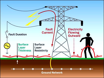
In the case of Step Potentials or step voltage, electricity will flow if a difference in potential exists between the two legs of a person. Calculations must be performed that determine how great the tolerable step potentials are and then compare those results to the step voltages expected to occur at the site.
Hazardous Step Potentials or step voltage can occur a significant distance away from any given site. The more current that is pumped into the ground, the greater the hazard. Soil resistivity and layering plays a major role in how hazardous a fault occurring on a specific site may be. High soil resistivities tend to increase Step Potentials. A high resistivity top layer and low resistivity bottom layer tends to result in the highest step voltages close to the ground electrode: the low resistivity bottom layer draws more current out of the electrode through the high resistivity layer, resulting in large voltage drops near the electrode. Further from the ground electrode, the worst case scenario occurs when the soil has conductive top layers and resistive bottom layers: in this case, the fault current remains in the conductive top layer for much greater distances away from the electrode.
Fault clearing time is an important factor to consider as well. The more time it takes the electric utility company to clear the fault, the more likely it is for a given level of current to cause the human heart to fibrillate.
An important note to remember is that most power companies use automated re-closers. In the event of a fault, the power is shut off and then automatically turned back on. This is done in case the faults occurred due to an unfortunate bird that made a poor choice in where to rest, or dust that may have been burned off during the original fault. A few engineers believe that Fibrillation Current for Step Potentials must be far greater than Touch Potentials, as current will not pass through any vital organs in the former case. This is not always true as personnel that receive a shock due to Step Potentials may fall to the ground, only to be hit again, before they can get up, when the automatic re-closers activate.
Touch Potential
When a fault occurs at a tower or substation, the current will pass through any metallic object and enter the earth. Those personnel “touching” an object in the vicinity of the GPR will be subjected to these touch voltages which may be hazardous.
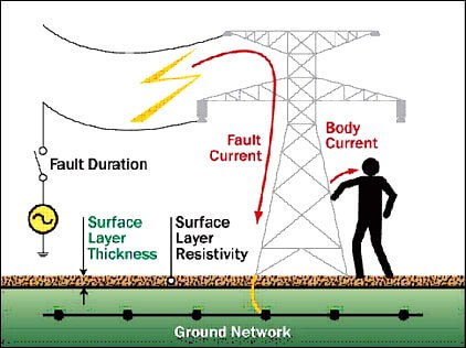
For example if a person happens to be touching a high-voltage tower leg when a fault occurs, the electricity would travel down the tower leg into the person’s hand and through vital organs of the body. It would then continue on its path and exit out through the feet and into the earth. Careful analysis is required to determine the acceptable Fibrillation Currents that can be withstood by the body if a fault were to occur.
Engineering standards use a one-meter (3.28 ft) reach distance for calculating Touch Potentials. A two-meter (6.54 ft) reach distance is used when two or more objects are inside the GPR event area. For example, a person could be outstretching both arms and touching two objects at once such as a tower leg and a metal cabinet. Occasionally, engineers will use a three-meter distance to be particularly cautious, as they assume someone may be using a power tool with a power cord 3 meters in length.
The selection of where to place the reference points used in the Touch Potential or touch voltage calculations are critical in getting an accurate understanding of the level of hazard at a given site. The actual calculation of Touch Potentials uses a specified object (such as a tower leg) as the first reference point. This means that the further away from the tower the other reference point is located, the greater the difference in potential. If you can imagine a person with incredibly long arms touching the tower leg and yet standing many dozens of feet away, you would have a huge difference in potential between their feet and the tower. Obviously, this example is not possible: this is why setting where and how far away the reference points used in the touch calculation is so important and why the one-meter rule has been established.
Mitigating Step and Touch Potential hazards is usually accomplished through one or more of the following three (3) main techniques:
- Reduction in the Resistance to Ground of the grounding system
- Proper placement of ground conductors
- The addition of resistive surface layers
Understanding the proper application of these techniques is the key to reducing and eliminating any Ground Potential Rise hazards. Only through the use of highly sophisticated 3-dimensional electrical simulation software that can model soil structures with multiple layers and finite volumes of different materials, can the engineer accurately model and design a grounding system that will safely handle high-voltage electrical faults.
Reducing Resistance to Ground
Reducing resistance to ground (RTG) of the site is often the best way to reduce the negative effects of any Ground Potential Rise event, where practical. The Ground Potential Rise is the product of the fault current flowing into the grounding system times the resistance to ground of the grounding system. Thus, reducing the Ground Potential Rise will reduce the Ground Potential Rise to the degree that the fault current flowing into the grounding system does increase in response to the reduced Ground Potential Rise. For example, if the fault current for a high-voltage tower is 5,000 amps and the resistance to ground of the grounding system is 10-ohms, the Ground Potential Rise will be 50,000 volts. If we reduce the resistance to ground of the grounding system down to 5-ohms and the fault current increases to 7,000 amps as a result, then the Ground Potential Rise will become 35,000 volts.
As seen in the example above, the reducing resistance to ground can have the effect of allowing more current to flow into the earth at the site of the fault, but will always result in lower Ground Potential Rise values and step and touch voltages at the fault location. On the other hand, further away from the fault location, at adjacent facilities not connected to the faulted structure, the increase in current into the earth will result in greater current flow near these adjacent facilities and therefore an increase in the Ground Potential Rise, touch voltages and step voltages at these facilities. Of course, if these are low to begin with, an increase may not represent a problem, but there are cases in which a concern may exist. Reducing the resistance to ground can be achieved by any number of means as discussed earlier in this chapter.
Proper Placement of Ground Conductors
A typical specification for ground conductors at high-voltage towers or substations is to install a ground loop around all metallic objects, connected to the objects; keep in mind that it may be necessary to vary the depth and/or distance that ground loops are buried from the structure in order to provide the necessary protection. Typically these ground loops require a minimum size of 2/0 AWG bare copper conductor buried in direct contact with the earth and 3-ft from the perimeter of the object, 18 inches below grade. The purpose of the loop is to minimize the voltage between the object and the earth surface where a person might be standing while touching the object: i.e., to minimize Touch Potentials.
It is important that all metallic objects in a GPR environment be bonded to the ground system to eliminate any difference in potentials. It is also important that the resistivity of the soil as a function of depth be considered in computed touch and step voltages and in determining at what depth to place conductors. For example, in a soil with a dry, high resistivity surface layer, conductors in this layer will be ineffective; a low resistivity layer beneath that one would be the best location for grounding conductors. On the other hand, if another high resistivity layer exists further down, long grounding rods or deep wells extending into this layer will be ineffectual.
It is sometimes believed that placing horizontal grounding loop conductors very close to the surface results in the greatest reduction in Touch Potentials. This is not necessarily so, as conductors close to the surface are likely to be in drier soil, with a higher resistivity, thus reducing the effectiveness of these conductors. Furthermore, while Touch Potentials immediately over the loop may be reduced, Touch Potentials a short distance away may actually increase, due to the decreased zone of influence of these conductors. Finally, Step Potentials are likely to increase at these locations: indeed, Step Potentials can be a concern near conductors that are close to the surface, particularly at the perimeter of a grounding system. It is common to see perimeter conductors around small grounding systems buried to a depth of 3-ft below grade, in order to address this problem.
Reducing Step and Touch Potential Hazards
One of the simplest methods of reducing Step and Touch Potential hazards is to wear Electric Hazard Shoes. When dry, properly rated electric hazard shoes have millions of ohms of resistance in the soles and are an excellent tool for personnel safety. On the other hand, when these boots are wet and dirty, current may bypass the soles of the boots in the film of material that has accumulated on the sides of the boot. A wet leather boot can have a resistance on the order of 100 ohms. Furthermore, it cannot be assumed that the general public, who may have access to the outside perimeter of some sites, will wear such protective gear.
Another technique used in mitigating Step and Touch Potential hazards is the addition of more resistive surface layers. Often a layer of crushed rock is added to a tower or substation to provide a layer of insulation between personnel and the earth. This layer reduces the amount of current that can flow through a given person and into the earth. Weed control is another important factor, as plants become energized during a fault and can conduct hazardous voltages into a person. Asphalt is an excellent alternative, as it is far more resistive than crushed rock, and weed growth is not a problem. The addition of resistive surface layers always improves personnel safety.