Rotating machinery requires speed sensing for functional systems such as control, monitoring, and safety. To ensure safe operation, it is especially important to monitor rotor speeds in turbine engines.
Inductive Sensor Operating Principle and Specification:
The inductive sensor also known as magnetic pickup sensor during the operation work, due to inductive effect, The sensor’s coil is producing the oscillating voltage.( one kind of sinusoidal waveform signal (∼) AC voltage).
When the trigger wheel with the teeth passes in enough close distance (G) to the pole pin of the sensor, the magnetic field surrounding the coil is changed. As the result of the magnetic field changes, in the coil a voltage is induced, which is proportional to the strength and rate of change of the magnetic field. One complete oscillation is produced for each tooth that passes beside to the sensor pole pin. Figure shows the basic integral components and the shape of the generated signal of an inductive sensor. The electrical resistance of the coil is typically in the range between 500 ohms and 1.500 ohms. The voltage signal produced by the sensor depends on the speed of the trigger wheel and the number of turns in the coil.
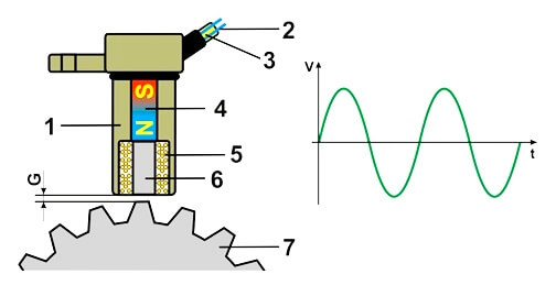
Parts of speed sensor:
- Sensor Housing
- Output signal wires
- Coaxial Coated protection
- Permanent magnet
- Inductive coil
- Pole pin
- Trigger wheel
- Air gap
Hall Effect Sensor Operating Principle:
Unlike inductive sensors, the output signal from a Hall Effect sensor is not affected by the rate of change of the magnetic field. The produced output voltage typically is in the range of mV and is additionally amplified by integrated electronics, fitted inside of the sensor housing.
Figure shows a typical build of a Hall Effect sensor. The final output voltage signal usually is in digital waveform pulses (square form). The output signal of the sensor can be either positive or negative with peak voltage usually up to 5 V or 12 V, depending upon the type of the integrated electronics and requirements of the used system. The amplitude of the output signal remains constant, only the frequency increases proportionally with rpm. Unlike inductive sensors which generate a voltage signal by itself, the Hall Effect sensors must be additionally supplied by external voltage needed for integrated electronics. The usual supplying voltage (+Vcc) is mainly 5 V but in some cases can be 12 V.
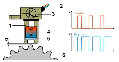
Parts of speed sensor:
- Sensor Housing
- Output wires (+Vcc, −Vcc and signal)
- Integrated electronics
- Permanent magnet
- Hall Effect device
- Trigger wheel
- Air gap
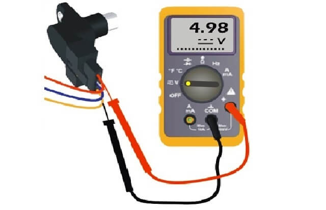
Inductive Sensor Diagnostics and Testing Procedure:
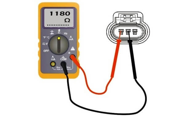
- Unplug the sensor and check that the electrical resistance of the inductive coil is roughly between 500 ohms and 1.500 ohms. If the reading value is drastically different, including zero or infinite, replace the sensor. (Also refer the vendor manual for resistance)
- Check the size of the air gap (G) between the sensor and the trigger wheel by the gauge filler the value should be: G ≈ 0.8 – 1.5 mm (0.03 – 0.06 inch). (Also refer the vendor manual for gap)
- Check the cleanliness of the sensor pin (sometimes may have cumulated metal turnings).
- Check the continuity and condition of the wires, connectors, terminals and the condition of the shielding.
Hall Effect Sensor Diagnostics and Testing Procedure:
- Check the power supply to the sensor. The usual supplying voltage is 5 V (in some cases can be 12 V). (Also refer the vendor manual)
- Check the size of the air gap (G) between the sensor and the trigger wheel, the value should be: G ≈ 0.8 – 1.5 mm (0.03 – 0.06 inch). (Also refer the vendor manual)
- Check the continuity and condition of the wires, connectors and terminals.
- Check the cleanliness of the sensor pin (sometimes may have cumulated metal turnings).
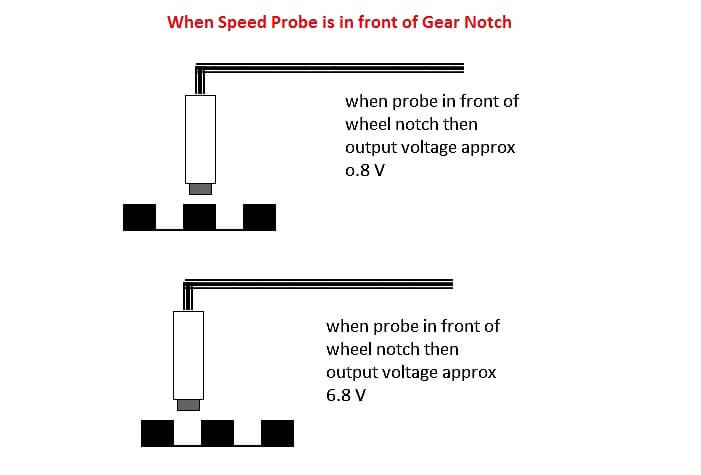
- Check that there is an output signal when a wheel is rotated.
NOTE: Unlike inductive sensors, at Hall a sensor the connector must be plugged in, because is needed power supply for integrated electronic components, which are inside of the sensor.
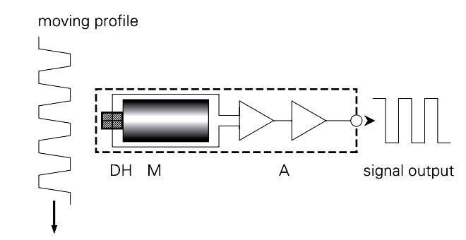
Differential-Hall-Effect Principle:
The Hall Effect (named for its discoverer) utilizes the fact that a magnetic field generates a voltage within a hall element. Its level is independent of its rate of change. The sensors include the necessary magnet (M) and the dual hall element (DH). With the profile passing by, the magnetic field varies, thereby creating the signal voltage within the hall element. Here it is important to keep in mind that the signal does not fade at low speed. The principle engages a twin chip hall element and the signal amplifier (A) uses only the difference between both. It is then amplified to provide the power square wave output.
Advantage of differential-Hall-Effect based Sensors: By its nature, this differential principle compensates target vibrations. And it diminishes the influence of external magnetic stray field. Both important aspects for a reliable signal.
Target Material: Any standard steel will be accepted, excluding stainless steel or any other non-magnetic material. Slots in a steel profile may be filled with such material, however, or a steel bolt inserted in a non-magnetic part.
Target Profile: A standard gear wheel is frequently used, as it is easy to get and to place on the shaft. A split gear wheel must have its division at the bottom between the teeth. Slots milled into a steel shaft or other rotor also results in a sharp and well defined signal. But care should be taken to have smooth surface and edges. The sensor with its sharp resolution might otherwise respond to scratches or other irregularities. Care however must be given to a regular position of slots, holes or bolts at the rotor. Irregular distances with result in fluctuating speed measurements. Hexagonal screw heads may result in an irregular pulse division. A slot or such like in the screw head may cause multiple pulses.
Single Channel Speed Monitor:
Measurement is based on the frequency of the pulse sequence representing the speed. Basic quantity is the time between one or more of its pulses. An automatic function determines this number, in order to maintain a minimum period of time for every measurement to be extended over. This time minimum is programmable to 5 milliseconds or more, thus establishing a corresponding averaging and stabilization of measurements. The corresponding speed value in terms of RPM, by which the display, the alarm circuit, and the analog output are reading, computes from these measurements. This process further considers the programmed application data (relation between machine speed and signal frequency).
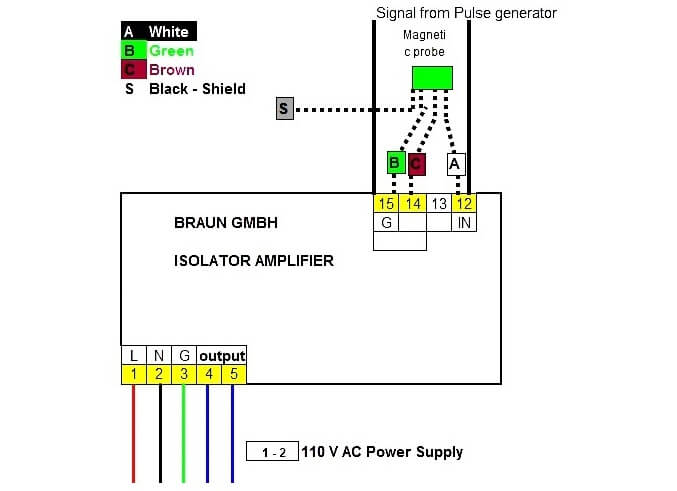
Wiring diagram:
Calculation of frequency:
Machine factor = No. of teeth x Gear ratio /60
Frequency = Span in RPM x Machine factor
How to install a speed probe:
When the prime mover shut down, turn the probe until it just touches the outside diameter of the gear. If the pickup has a 5/8-18 thread, one 360° turn counterclockwise will move the pickup out 0.0555 inch (1.41 mm). The metric pickup will move 1.5 mm per turn. If the pickup has a 3/4-20 mounting thread, the pickup will move out 0.050 inch (1.27 mm) per turn. Screw out the amount required for the desired gap. If possible, run the gear slowly through 360° rotation to check the clearance of the pickup. When the gap is set, tighten the jam nut securely against the housing or bracket so the pickup cannot turn in or out.