A resistor is one of the most fundamental components in electronics. Its purpose is to impede a flow of current and impose a voltage reduction. It consists of two wires or conductors attached at opposite ends or sides of a relatively poor electrical conductor, the resistance of which is measured in ohms, universally represented by the Greek omega symbol, Ω.
Resistor Symbols
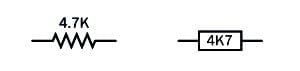
The left one is more common in the used. The 4.7K value was chosen arbitrarily.
Schematic symbols that represent a resistor are shown in the figure above (Left: The traditional schematic symbol. Right: The more recent European equivalent). Letters K or M indicate that the value shown for the resistor is in thousands of ohms or millions of ohms, respectively. Where these letters are used in Europe, and sometimes in the US, they are substituted for a decimal point. Thus, a 4.7K resistor may be identified as 4K7, a 3.3M resistor may be identified as 3M3, and so on. (The numeric value in the figure above was chosen arbitrarily.)
Function Of Resistor
A resistor is commonly used for purposes such as limiting the charging rate of a capacitor; providing appropriate control voltage to semiconductors such as bipolar transistors; protecting LEDs or other semiconductors from excessive current; adjusting or limiting the frequency response in an audio circuit (in conjunction with other components); pulling up or pulling down the voltage at the input pin of a digital logic chip; or controlling a voltage at a point in a circuit. In this last application, two resistors may be placed in series to create a voltage divider.
A potentiometer may be used instead of a resistor where variable resistance is required.
Sample resistors of various values are shown in the following figure.
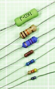
From top to bottom, their power dissipation ratings are 3W, 1W, 1/2W, 1/4W, 1/4W, 1/4W, and 1/8W. The accuracy (tolerance) of each resistor, from top to bottom, is plus-or-minus 5%, 5%, 5%, 1%, 1%, 5%, and 1%. The beige-colored body of a resistor is often an indication that its tolerance is 5%, while a blue-colored body often indicates a tolerance of 1% or 2%. The bluebodied resistors and the dark brown resistor contain metal-oxide film elements, while the beigebodied resistors and the green resistor contain carbon film. For more information on resistor values, see the upcoming Values section.
Working Principle Of Resistor
In the process of impeding the flow of current and reducing voltage, a resistor absorbs electrical energy, which it must dissipate as heat. In most modern electronic circuits, the heat dissipation is typically a fraction of a watt.
If R is the resistance in ohms, I is the current flowing through the resistor in amperes, and V is the voltage drop imposed by the resistor (the difference in electrical potential between the two contacts that are attached to it), Ohm’s law states:
V = I / R
This is another way of saying that a resistor of 1Ω will allow a current of 1 amp when the potential difference between the ends of the resistor is 1 volt.
If W is the power in watts dissipated by the resistor, in a DC circuit:
W = V * I
By substitution in Ohm’s law, we can express watts in terms of current and resistance:
W = I2 / R
We can also express watts in terms of voltage and resistance:
W = V2 * R
These alternates may be useful in situations where you do not know the voltage drop or the current, respectively.
Approximately similar relationships exist when using alternating current, although the power will be a more complex function of resistor.
Applications Of Resistors
Some of the most common applications for a resistor are listed here.
Use A Resistor In Series With LED
To protect an LED from damage caused by excessive current, a series resistor is chosen to allow a current that does not exceed the manufacturer’s specification. In the case of a single throughhole LED (often referred to as an indicator), the forward current is often limited to around 20mA, and the value of the resistor will depend on the voltage being used.
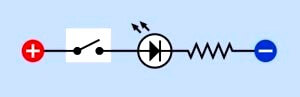
Fig : A series resistor is necessary to limit the current that passes through an LED.
When using high-output LEDs (which may contain multiple elements in a single 5mm or 10mm package), or LED arrays that are now being used for domestic lighting, the acceptable current may be much greater, and the LED unit may contain its own current-limiting electronics. A datasheet should be consulted for details.
Use A Resistor For Current Limiting With A Transistor
In the following figure, a transistor is switching or amplifying current flowing from B to C. A resistor is used to protect the base of the transistor from excessive current flowing from point A. Resistors are also commonly used to prevent excessive current from flowing between B and C.
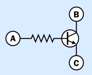
Fig : A resistor is typically necessary to protect the base of a transistor from excessive current.
Pullup And Pulldown Resistors
When a mechanical switch or pushbutton is attached to the input of a logic chip or microcontroller, a pullup or pulldown resistor is used, applying positive voltage or grounding the pin, respectively, to prevent it from “floating” in an indeterminate state when the switch is open. In the following figure, the upper schematic shows a pulldown resistor, whereas the lower schematic shows a pullup resistor.
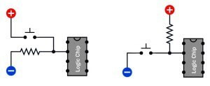
A pulldown resistor (top) or pullup resistor (bottom) prevents an input pin on a logic chip or microcontroller from “floating” in an indeterminate state when the button is not being pressed.
A common value for either of them is 10K. When the pushbutton is pressed, its direct connection to positive voltage or to ground easily overwhelms the effect of the resistor. The choice of pullup or pulldown resistor may depend on the type of chip being used.
Resistor Used For Audio Tone Control
A resistor-capacitor combination can limit the high-frequency in a simple audio tone-control circuit, as shown in the following figure.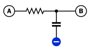
This configuration may be used to remove high frequencies from an audio signal. It is known as a low-pass filter because low frequencies are passed from A to B.
Beneath a signal travelling from A to B, a resistor is placed in series with a capacitor that passes high frequencies to ground. This is known as a low-pass filter.
Resistor Use In RC Network
A resistor will adjust the charge/discharge time when placed in series with a capacitor, as in the following figure.
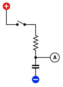
In an RC (resistor-capacitor) network, a resistor limits the rate of increase in potential of the capacitor, measured at A, when the switch is closed.
When the switch closes, the resistor limits the rate at which the capacitor will charge itself from the power supply. Because a capacitor has an ideally infinite resistance to DC current, the voltage measured at point A will rise until it is close to the supply voltage.
Resistor Used For Voltage Divider
Two resistors may be used to create a voltage divider (see inthe following figure).
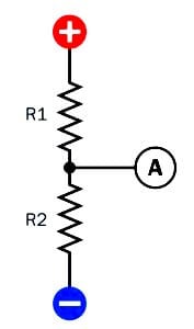
In a DC circuit, a pair of resistors may be placed in series to function as a voltage divider. The voltage measured at A will be lower than the supply voltage, but above ground potential.
If Vin is the supply voltage, the output voltage, Vout, measured at point A, is found by the formula:
Vout = Vin * (R2 / (R1 + R2))
In reality, the actual value of Vout is likely to be affected by how heavily the output is loaded.
If the output node has a high impedance, such as the input to a logic chip or comparator, it will be more susceptible to electrical noise, and lower-value resistors may be needed in the voltage divider to maintain a higher current flow and maintain stability in the attached device.
Resistors In Series
If resistors in series have values R1, R2, R3 . . . the total resistance, R, is found by summing the individual resistances:
R = R1 + R2 + R3. . .
The current through each of the resistors will be the same, whereas the voltage across each of them will vary proportionately with its resistance. If the supply voltage across the series of resistors is VS, and the total of all the resistor values is RT, and the resistance of one resistor is R1, the voltage across that resistor, V1, will be given by the formula:
V1 = VS * (R1 / RT)
Resistors In Parallel
Where two or more resistors (R1, R2, R3 . . . ) are wired in parallel, their total resistance, R, is found from the formula:
1/R = ( 1/R1 ) + ( 1/R2 ) + ( 1/R3 ). . .
Suppose that R1, R2, R3 . . . all have the same individual resistance, represented by RI, and the number of resistors is N. Their total resistance, RT, when wired in parallel, will be:
RT = RI / N
If each resistor has an equal resistance and also has an equal individual rating in watts (represented by WI), the total wattage (WT) that they can handle when wired in parallel to share the power will be:
WT = WI * N
Therefore, if an application requires highwattage resistors, multiple lower-wattage, higher-value resistors may be substituted if they are wired in parallel—and may even be cheaper than a single high-wattage wire-wound resistor.
For example, if a 5W, 50Ω resistor is specified, 10 resistors can be substituted, each rated at 0.5W and 500Ω. Bear in mind that if they are tightly bundled, this will interfere with heat dissipation of resistor.