Read the Modbus communication interview questions prepared for your interview.
Modbus Communication Interview Questions and Answers

What is Modbus?
Modbus is a serial communication protocol developed by Modicon published by Modicon® in 1979 for use with its programmable logic controllers (PLCs).
In simple terms, it is a method used for transmitting information over serial lines between electronic devices.
The device requesting the information is called the Modbus Master and the devices supplying information are Modbus Slaves.
In a standard Modbus network, there is one Master and up to 247 Slaves, each with a unique Slave Address from 1 to 247. The Master can also write information to the Slaves.
Modbus is an open communications protocol commonly used in industrial manufacturing that allows for communication between devices.
With Modbus, devices from different manufacturers can be integrated in to the same device management system. Modbus also enables remote read and write functionality from a device.
What is it used for?
Modbus is used to gather data from many different devices for simultaneous observation, configuration, or data archiving.
If you have a large campus with many buildings, or even buildings spread across a region, Modbus can be used to monitor those buildings from one central point.
Modbus is an open protocol, meaning that it’s free for manufacturers to build into their equipment without having to pay royalties. It has become a standard communications protocol in industry, and is now the most commonly available means of connecting industrial electronic devices. It is used widely by many manufacturers throughout many industries.
Modbus is typically used to transmit signals from instrumentation and control devices back to a main controller or data gathering system, for example a system that measures temperature and humidity and communicates the results to a computer.
Modbus is often used to connect a supervisory computer with a remote terminal unit (RTU) in supervisory control and data acquisition (SCADA) systems. Versions of the Modbus protocol exist for serial lines (Modbus RTU and Modbus ASCII) and for Ethernet (Modbus TCP).
How does it work?
Modbus is transmitted over serial lines between devices. The simplest setup would be a single serial cable connecting the serial ports on two devices, a Master and a Slave.
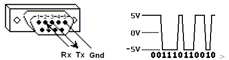
The data is sent as series of ones and zeroes called bits. Each bit is sent as a voltage. Zeroes are sent as positive voltages and a ones as negative. The bits are sent very quickly.
A typical transmission speed is 9600 baud (bits per second).
What is hexadecimal?
When troubleshooting problems, it can be helpful to see the actual raw data being transmitted.
Long strings of ones and zeroes are difficult to read, so the bits are combined and shown in hexadecimal. Each block of 4 bits is represented by one of the sixteen characters from 0 to F.
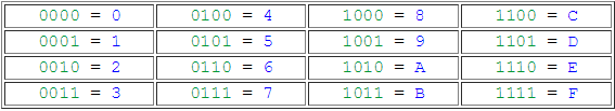
Each block of 8 bits (called a byte) is represented by one of the 256 character pairs from00 to FF.
What is ASCII?
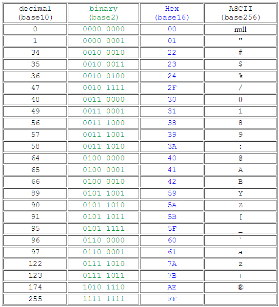
ASCII stand for American Standard Code for Information Interchange.
In the same way that every 4 bits can be combined and represented by one of sixteen hexadecimal characters from 0 to F, every 8 bits (every byte) can be combined and represented by one of 256 ASCII characters, including the common keyboard characters.
For example, some of the values for ASCII characters are…
How is data stored in Standard Modbus?
Information is stored in the Slave device in four different tables.
Two tables store on/off discrete values (coils) and two store numerical values (registers).
The coils and registers each have a read-only table and read-write table.
Each table has 9999 values.
Each coil or contact is 1 bit and assigned a data address between 0000 and 270E.
Each register is 1 word = 16 bits = 2 bytes and also has data address between 0000 and270E.
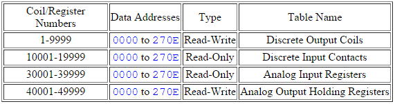
Coil/Register Numbers can be thought of as location names since they do not appear in the actual messages. The Data Addresses are used in the messages.
For example, the first Holding Register, number 40001, has the Data Address 0000.
The difference between these two values is the offset.
Each table has a different offset. 1, 10001, 30001 and 40001.
What is the Slave ID?
Each slave in a network is assigned a unique unit address from 1 to 247.
When the master requests data, the first byte it sends is the Slave address. This way each slave knows after the first byte whether or not to ignore the message.
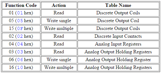
What is a function code?
The second byte sent by the Master is the Function code.
This number tells the slave which table to access and whether to read from or write to the table.
What is a CRC?
CRC stands for Cyclic Redundancy check. It is two bytes added to the end of every modbus message for error detection. Every byte in the message is used to calculate the CRC.
The receiving device also calculates the CRC and compares it to the CRC from the sending device. If even one bit in the message is received incorrectly, the CRCs will be different and an error will result.
What is byte and word ordering?
The Modbus specification doesn’t define exactly how the data is stored in the registers.
Therefore, some manufacturers implemented modbus in their equipment to store and transmit the higher byte first followed by the lower byte. (AE before 41).
Alternatively, others store and transmit the lower byte first (41 before AE).
Similarly, when registers are combined to represent 32-bit data types, Some devices store the higher 16 bits (high word) in the first register and the remaining low word in the second (AE41 before 5652) while others do the opposite (5652 before AE41)
It doesn’t matter which order the bytes or words are sent in, as long as the receiving device knows which way to expect it.
For example, if the number 2,923,517,522 was to be sent as a 32 bit unsigned integer, it could be arranged any of these four ways. example
AE41 5652 high byte first high word first “big endian”
5652 AE41 high byte first low word first
41AE 5256 low byte first high word first
5256 41AE low byte first low word first “little endian”
What is a Modbus Map?
A modbus map is simply a list for a slave device that defines
- what the data is (eg. pressure or temperature readings)
- where the data is stored (which tables and data addresses)
- how the data is stored (data types, byte and word ordering)
Some devices are built with a fixed map that is defined by the manufacturer. While other devices allow the operator to configure or program a custom map to fit their needs.
How does 2-byte slave addressing work?
Since a single byte is normally used to define the slave address and each slave on a network requires a unique address, the number of slaves on a network is limited to 256. The limit defined in the modbus specification is even lower at 247.
To get beyond this limit, a modification can be made to the protocol to use two bytes for the address. The master and the slaves would all be required to support this modification. Two byte addressing extends the limit on the number of slaves in a network to 65535.
By default, the Simply Modbus software uses 1 byte addressing. When an address greater than 255 is entered, the software automatically switches to 2 byte addressing and stays in this mode for all addresses until the 2 byte addressing is manually turned off.
What is Modbus TCP/IP protocol?
TCP/IP is the common transport protocol of the Internet and is actually a set of layered protocols, providing a reliable data transport mechanism between machines.
Ethernet has become the de facto standard of corporate enterprise systems, so it comes as no surprise that it has also become the de facto standard for factory networking. Ethernet is not a new technology. It has matured to the point that the cost of implementing this network solution has been dropping to where its cost is commensurate with those of today’s field-buses.
Using Ethernet TCP/IP in the factory allows true integration with the corporate intranet and MES systems that support the factory. To move Modbus into the 21st century, an open Modbus TCP/IP specification was developed in 1999. The protocol specification and implementation guide are available for download (www.modbus.org/specs).
Combining a versatile, scaleable, and ubiquitous physical network (Ethernet) with a universal networking standard (TCP/IP) and a vendor-neutral data representation, Modbus gives a truly open, accessible network for exchange of process data. It is simple to implement for any device that supports TCP/IP sockets.
Where is Modbus TCP/IP used?
Modbus TCP/IP has become ubiquitous because of its openness, simplicity, low-cost development, and minimum hardware required to support it.
There are several hundred Modbus TCP/IP devices available in the market – more being developed each year. It is used to exchange information between devices, monitor, and program them. It is also used to manage distributed I/Os, being the preferred protocol by the manufacturers of this type of devices.
Why should I use Modbus TCP/IP?
When it comes to choosing a network for your device, Modbus TCP/IP offers several significant advantages:
Simplicity:
Modbus TCP/IP simply takes the Modbus instruction set and wraps TCP/IP around it. If you already have a Modbus driver and you understand Ethernet and TCP/IP sockets, you can have a driver up and running and talking to a PC in a few hours.
Development costs are exceptionally low. Minimum hardware is required, and development is easy under any operating system.
Standard Ethernet:
There are no exotic chipsets required and you can use standard PC Ethernet cards to talk to your newly implemented device.
As the cost of Ethernet falls, you benefit from the price reduction of the hardware, and as the performance improves from 10 to 100 Mb and soon to 1 Gb, your technology moves with it, protecting your investment.
You are no longer tied to one vendor for support, but benefit from the thousands of developers out there who are making Ethernet and the Internet the networking tools of the future. This effort has been complemented opportunely with the assignment of the well-known Ethernet port 502 for the Modbus TCP/IP protocol.
Open:
The Modbus protocol was transferred from Schneider Electric to the Modbus Organization in April 2004, signaling a commitment to openness.
The specification is available free of charge for download, and there are no subsequent licensing fees required for using Modbus or Modbus TCP/IP protocols.
Additional sample code, implementation examples, and diagnostics are available on the Modbus TCP toolkit, a free benefit to Modbus Organization members and available for purchase by nonmembers
Availability of many devices:
Interoperability among different vendors’ devices and compatibility with a large installed base of Modbus-compatible devices makes Modbus an excellent choice.
Can I use Modbus TCP/IP over the Internet?
Modbus TCP/IP is an Internet protocol. The fact that TCP/IP is the transport protocol of the Internet automatically means that Modbus TCP/IP can be used over the Internet. It was designed to reach this goal.
In practical terms, this means that a Modbus TCP/IP device installed in Europe can be addressed over the Internet from anywhere in the world. The implications for an equipment vendor or an end-user are endless.
Performing maintenance and repair on remote devices using a PC and browser reduces support costs and improves customer service.
Logging onto a plant’s control system from home allows the maintenance engineer to maximize his plant’s uptime and reduces time in the field.
Managing geographically distributed systems becomes easy using commercially available internet/intranet technologies.
Can existing Modbus devices communicate over Modbus TCP/IP?
Since Modbus TCP/IP is simply Modbus protocol with a TCP wrapper, it is very simple for existing Modbus devices to communicate over Modbus TCP/IP.
A gateway device is required to convert from the current physical layer (RS232, RS485 or others) to Ethernet and to convert Modbus protocol to Modbus TCP/IP.
Such a gateway device could be implemented using a PC. Commercial products to do this are available from several different manufactures.
The Modbus device database can help you identify gateways and other Modbus devices.
Explain Modbus ® protocol?
Modbus Protocol is a messaging structure developed by Modicon in 1979. It is used to establish master-slave/client-server communication between intelligent devices. It is a de facto standard, truly open and the most widely used network protocol in the industrial manufacturing environment.
It has been implemented by hundreds of vendors on thousands of different devices to transfer discrete/analog I/O and register data between control devices. It’s a lingua franca or common denominator between different manufacturers.
One report called it the “de facto standard in multi-vendor integration”. Industry analysts have reported over 7 million Modbus nodes in North America and Europe alone.
What is a master-slave network?
A master-slave technique is one in which only one device (the master) can initiate transactions (queries). The other devices (the slaves) respond by supplying the requested data to the master, or by taking the action requested in the query.
Typical master devices include touch screens or PCs running Wonderware, Intellution or LabVIEW while slaves include PLCs and smart devices such as PID controllers or meters.
How to connect MODBUS devices together in a network?
RS-232 outputs cannot be connected together. To create a network the devices must use a RS-485 network and have a unique slave address.
What are RS-232, RS-422 and RS-485 and how are they different?
These are standards for serial communications that define the pin outs, cabling, signal levels, transmission baud rates and parity checking.
- RS-232 only allows for one master and one slave and is limited to distances of up to 15 meters.
- RS-422 can address up to 10 slaves using four wires (full duplex) and has a distance capacity of 4000 feet.
- RS-485 can address up to 32 slaves using either a two wire (half duplex) or four wire system (full duplex) and has a distance capacity of 4000 meters.
A common mistake is to confuse the electrical standard with the protocol. Protocols define how the data is structured while the electrical standards determine how the data is physically transmitted.
There are many different protocols (i.e. Modbus, DF1, AS511) that can be used on RS-232, RS-422 or RS-485 wired systems.
How many slaves can there be?
- RS-232 only allows for one slave.
- RS-422 can address up to 10 slaves.
- RS-485 can address up to 32 slaves.
The address can be a unique number between 1 and 247 for all these systems.
How far away can devices be away from each other?
- For an RS-232 connection the maximum distance is 15 meters.
- For RS-422 and RS485 connections the maximum distance is 4000 meters.
- Repeaters can be used to increase the distance.
What sort of cable to be used for modbus?
A shielded #18AWG cable with twisted pairs is recommended. The shield should be grounded on one end only.
What are the communication settings?
This is unique to each device. Consult the manufacturer’s manual. A typical setup has
| Baud Rate: | 9600 |
| Parity: | Even |
| Data Bits: | 8 |
| Stop Bits: | 1 |
What are ASCII Chart “>ASCII and RTU modes?
ASCII (American Standard Code for Information Interchange) uses 10 bits of data comprised of 7 data bits, 1 parity bit, 1 start bit and 1 stop bit. It uses LRC (Longitudinal Redundancy Check) for error checking.
The advantage of ASCII is it allows up to 1 second time intervals to occur between character transmissions without generating an error. It’s most useful when communication is slow.
RTU mode (Remote Terminal Unit) contains 4 bit hex characters divided up into 8 data bits, 1 parity bit, 1 start bit, and 1 stop bit. It uses CRC (Cyclical Redundancy Check) for error checking.
RTU has the advantage that it can send more data in the same amount of time but it has to be in a continuous stream (no delays between characters).
What is a coil?
This is a single bit of information indicating either an ON (1) or OFF (0) state. Types of coils include valve states, alarms/warnings and status.
What is a register?
This is a 16-bit data field. The data can be in binary (decimal), hex or BCD format. Types of register data include temperatures, pressures, times and PID variables.
Why is the addressing off by one?
Some Modbus master devices compute register locations differently so the actual address might be shifted by one. This is often referred to as “adding the offset”.
How can I test the MODBUS connection?
The best way to do this is to have a separate computer/laptop with the ability to monitor MODBUS by acting as a Master station.
The only cable required to test MODBUS is a three conductor, wired to one end with a standard 9 pin connector for the computer com port and the other end loose to tie into the customer interface terminals.
The 9 pin terminal 2 is Rx, terminal 3 is Tx, and 5 is GND (or Common). So the Rx on one end goes to the Tx on the other and vice versa, and the GND goes to GND.
To test an RS485 connection first establish that the RS232 side is working by disconnecting the RS232/485 converter and testing by the above method.
Once the RS232 side is confirmed as working the only way to verify the RS485 connection with a PC is to use another RS232/485 converter to convert the signal back into a RS232 signal that the PC can read.
A converter on another PLC can be used for testing but the RS232 side of the converter must be disconnected first before using the PC.
I’m getting communication time out errors and I can’t get the device to communicate with my software? What could be wrong?
- Transmit and receive signals can often be verified by watching the transmit and receive lights on the Modbus components.
- The communication parameters are not set up correctly on the device. Check the settings match for slave address, baud rate, stop bit and parity.
- Make sure the host software has the same configuration
- The transmit and receive wires are crossed. Try switching the wires as it will not cause any damage.
- Check the conductivity on each wire for loose connections or broken wires.
- High power lines or improper grounding is causing noise in the system. Are the communication cables shielded and is the shield grounded on one end.
The MODBUS data does not match what is on the screen. What is wrong?
- The addressing may be off by one depending upon how the host software handles addressing.
- Slow communications may delay updates on MODBUS data.
- Host software is not configured to continually poll for new readings.
- The data format may be set up incorrectly. Refer to the user manual’s MODBUS table for the data formatting.
- Typically the data will be in binary/decimal format. In certain situations the data may be in hexadecimal.
- Some data has implied decimal places so that a value of 432.1 will be 4321 in MODBUS.
- Some large numbers may require two addresses. This is called a double word. The low address (word) will contain the first four places while the higher address (word) will contain the upper four digits. For a quick conversion take the (high word X 10000) + low word.
- Sometimes scaling is required to derive the proper number. The scaling is indicated on the MODBUS table where the actual data is given and then the scale value. For example, if the actual reading is from 0 to 4095 and the scaling is from 0 to 100 then the actual value will have to be divided by 40.95 to get the proper scaling.
What type of protocol is Modbus TCP?
Modbus TCP is an open protocol and is widely uses across building automation, intelligent buildings, and industrial automation networks
How are real (floating point) and 32-bit data encoded in Modbus RTU messages?
The Modbus RTU protocol itself was designed based on devices with a 16-bit register length. Consequently, special considerations were required when implementing 32-bit data elements.
This implementation settled on using two consecutive 16-bit registers to represent 32 bits of data or essentially 4 bytes of data. It is within these 4 bytes of data that single-precision floating point data can be encoded into a Modbus RTU message.
Also Read: Profibus Communication Interview Questions
Thank you sir for providing excellent guidance for interviews.
HELLO, my fryend!
Congrats….
Jefferson Leonardo(linkedin)
I am techician instrument and eletric. GOOD!
super sir but nomma deep ah tamil mozhi ya use pannathinga puriya maatikuthu
How to reduce deviation in radar level transmitter via Hart communicator????
via Hart communication