Losses are the wastage of energy in the device which will affect the overall efficiency of the device. So the losses of the device should be known to design the component with minimum losses. Transformer is an electrical isolation component which transfers the power from primary to secondary without any physical contact. In power transmission from primary and secondary, there are losses in the transformer which are bases on load of the transformer i.e. No-load losses and Load Losses.
Pt = PNL + PLL
Where.
Pt = Total Losses in the transformer
PN L = No-load losses in the transformer
PLL = Load losses in the transformer.
No Load Loss of Transformer
No- Load losses are the steady losses which will not vary according to the load on the transformer. No-load losses are caused by the magnetizing current needed to energize the core of the transformer. When the winding is energized, the exciting current consists of real component (core loss) and a reactive component (energy stored momentarily in the winding inductance). These losses can be minimized by the perfect design of the component and the No-load losses are categorized as shown below
- Hysteresis losses in the core lamination
- Eddy current losses in the core lamination’s
- Dielectric losses in the transformer components during excitation.
- I2R losses due to no-load current in the primary and secondary windings.
For distribution transformers no load losses are typically less than 5% of the rated current. Hysteresis losses and eddy current losses contribute over 99% of the no-load losses.
Load Losses
Load losses are caused by the winding impedance and vary according to the loading on the transformer. Transformer load losses can be divided into two parts:
- Loss used by transformer winding electrical resistance when load currents flow
- Eddy current losses caused by currents circulating within the winding conductors
They include heat losses (I2R) and eddy currents in the primary and secondary conductors of the transformer. Heat losses, or I2R losses, in the winding materials contribute the largest part of the load losses. They are created by resistance of the conductor to the flow of current or electrons.
How to measurement of Losses
Measurements of transformer loss are usually conducted during open-circuit and short-circuit tests. With the open-circuit test (load = 0) the measured losses are the no-load loss. During the short-circuit test the secondary is shorted and primary voltage adjusted to achieve a full load current flow. Short-circuit tests give the total transformer loss from which the load loss can be calculated by subtracting the no load loss.
Hysteresis losses in transformer
Magnetic Hysteresis
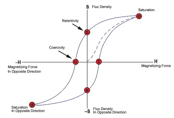
The phenomenon of magnetization lagging behind the field producing it is called magnetic hysteresis. It is derived from Greek word hysteresis (to lag). Every Ferromagnetic material used in transformer cores exhibits hysteresis phenomena. The hysteresis curve of a magnetic material is shown in the figure
By applying external magnetic field the magnetic material will get magnetized. The extent the material gets magnetized depends on the applied field and the permeability of the material (µr). The magnetization, flux density inside material.
B = µo*µr*H, M = (µr-1)*H
Ferromagnetic materials have high magnetic permeability’s and hence can be magnetized used. Starting from zero external field, as the external field is increased the magnetization increases till it reaches saturation. After the field inside the material reaches saturation field further there will not be any increase in thee magnetization even after the external field is increased.
Now if we decrease the field the flux density decreases. But at zero external fields there exists remanent magnetization inside the material. In order to make the flux density inside the material zero we should apply magnetic filed in the direction opposite to the field applied before. The external field that should be applied to make the flux density inside the material zero is called coercive field denoted by Hc. It is obvious from the B-H curve that magnetization and the flux density inside the material lag behind the applied field.
Explanation of Hysteresis
Magnetic hysteresis can be explained as follows: Ferromagnetic materials such as iron consist of domains in their internal structure. The size of the domain will be ranging from 1 micro m to 1 mm. These domains consist of a number of magnetic dipoles which are parallel with respect to one another inside the domain. Every atom in ferromagnetic material has contains of unpaired spinning electrons which acts as magnetic dipoles. Hence every atom has non zero magnetic moment associated with it. Due to random orientation of domains at no applied magnetic field the net magnetization in a ferromagnetic material will be zero.
When an external magnetic field is applied all these domains orient in the direction of magnetic field which gives rise to net magnetic field. Now the external field is removed, after the removal of external filed most of the domains again orient randomly. But some of the domains retain their orientation due to crystal defects (dislocations) giving rise to permanent magnetization. As the applied magnetic field intensity varies periodically, the hysteresis loop is traced once. To make the field inside the material zero an external magnetic field opposite to the direction of magnetization of iron should be applied. So in order to achieve this demagnetization and magnetization of domains extra work is being done which is termed as hysteresis loss.
Quantification of Hysteresis Loss
The total area inside the hysteresis loss is a measure of hysteresis losses of core. The work done on the core to neutralize the field inside core appears as hysteresis loss. The hysteresis losses of core per unit volume of core is given as
![]()
Hence the total hysteresis losses = Total area inside hysteresis loop*volume of core.
Therefore the materials with less area inside the hysteresis loop are preferred for transformer cores.
According to Steinmetz’s formula, the heat energy dissipated due to hysteresis is given by
Wh=ηβmax1.6 , and,
Hysteresis loss is thus given by
Ph≈ Whf ≈ηfβmax1.6
Where,
f is the frequency,
η is the hysteresis coefficient and
βmax is the maximum flux density, the empirical exponent of which varies from about 1.4 to 1 .8 depending on the material used for core but is often given as 1.6 for iron.
Remedies to reduce hysteresis loss
Air core transformer eliminates loss due to hysteresis in the core material but has more leakage flux. Air core provides very low inductance in most situations. Hence it is not a plausible solution.
Another remedy is to use soft magnetic materials with low hysteresis, such as silicon steel, steel alloys, Mn-Zn ferrite,. Soft magnetic materials are optimal to be used in transformer core because of following advantages
- High saturation magnetization, hence the core saturation happens at higher magnetic fields
- They are characterized by Low coercivity and remanent magnetic flux density, which means low hysteresis losses.
- High resistivity
- High magnetic permeability’s e.t.c.
Eddy currents Losses in Transformer
Origin or Cause of eddy currents
When time varying magnetic flux flows in the Ferromagnetic core, an emf is induced in the core in accordance with the Faraday’s law.
Φ = magnetic flux =
where
B is magnetic flux density,
S is the surface though which flux flows.
According to Lenz’s law this EMF is induced in a direction opposing the original field producing it. This induced emf will produce local currents in the conducting core normal to the magnetic flux these currents are called eddy currents.
Skin effect
The field produced by this time varying eddy currents try to nullify the fields inside the core. Hence these currents flow within the skin depth of core near the surface. This is termed as skin effect. The magnitude of Ac current density inside the core can be approximated as
|J| = Jo*e (-Z*α)
Where the direction of energy propagation is thought to be in Z direction,
α is the attenuation constant = (ω*µo*µr*σ/2) and has the units of m-1.
ω = 2*pi*f
where f is the frequency of alternating current,
µr is the relative magnetic permeability of core,
σ is the conductivity of core,
µo is the permeability of vacuum = 4*∏*10-7 H⋅m−1
The skin depth is defined as the distance within which the fields reduce to 1/e of its maximum value. Skin depth is the characteristic of the material which also depends on the frequency of the time varying magnetic field. The skin depth is denoted by δ and is given as
Skin depth δ = 1/ α = (2/( ω*µo*µr*σ))
The resistance of the core for alternating currents will be different from the DC resistance (L/(σ*A)) where L is the length of core and A is the area of the core. The effective resistance due to skin effect for long cylindrical conductor such as a wire, having a diameter D large compared to δ, has a resistance approximately that of a hollow tube with wall thickness δ carrying direct current is given as
R = L/ (σ*∏*D* δ)
Due to finite resistivity of core these eddy currents leads to power dissipation in the core.
Quantification of Eddy current losses
According to Steinmetz’s formula the eddy current losses in a transformer
Pe = Kef2Kf2Bm2 watts
Where Ke = Eddy Current Constant.
Kf = form Constant.
The total core losses in transformer is given as Pc = Ph + Pe
= Kh*f*Bmn+ Kef2Kf2Bm2
Where
f is the frequency of the external magnetic field,
B is flux density,
Kh, Ke and n are the coefficients, which depend on the lamination material, thickness, conductivity, as well as other factors. However, this formula is only applicable under the assumption that the maximum magnetic flux density of 1.0 Tesla is not exceeded and the hysteresis loop is under the static situation.
Eddy current losses increases with increasing frequency and increases with increasing conductivity.
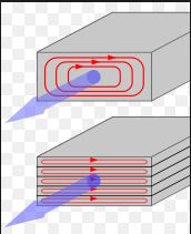
Remedies to reduce eddy current losses
In transformers eddy current loss is undesirable and can be reduced by using the core materials that havehigh permeability but low conductivity. Soft ferrites are such materials.
For low frequency high power applications laminated cores out of stacked ferromagnetic sheets each electrically insulated from its neighbors by thin oxide coatings (insulator). The insulating coatings parallel to the direction of magnetic flux so that eddy currents normal to the flux is restricted to the laminated sheets. The eddy current power loss decreases as the number of lamination’s increases.