Transfer of the immediate discharge of the electrical energy directly to the earth by means of the low resistance path is known as the earthing.
Instrumentation Earthing
Main objective of the earthing system in plant is described as below:
- It provides low impedance path to ensure the proper function of system under fault condition
- It ensures that personnel are not exposed to unsafe potential due to uncleared fault
- It ensures compliance to EMC requirements
- IS earth avoids ignition sources in Hazardous Area.
Items or equipment which require earthing, are but not limited to below,
- field instruments,
- control system cabinets,
- analyzer shelters,
- junction boxes,
- enclosures,
- ducts,
- cable trays,
- stanchions,
- field local panels,
- Consoles,
- Motors,
- Tanks,
- vessels,
- pipes,
- steel structure, etc.
This article mainly focuses on earthing requirements for instrumentation items of any industrial plant.
Types
There are mainly 3 types of earthing systems provided for instrumentation.
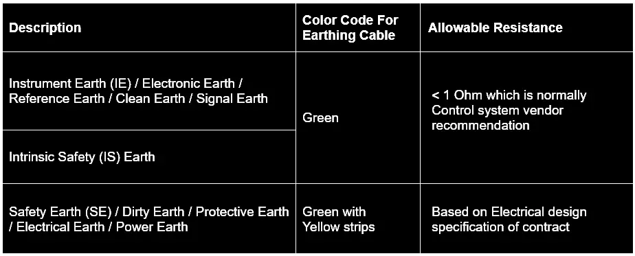
- Safety Earth (SE) / Dirty Earth / Protective Earth / Electrical Earth / Power Earth
- Instrument Earth (IE) / Electronic Earth / Reference Earth / Clean Earth / Signal Earth
- Intrinsic Safety (IS) Earth for IS circuit. This is only required when you have IS instruments.
Instrument Earth
The primary aim of the instrument earth/signal earth is to provide a low impedance path to the noise currents induced by RFI/EMI, which may result in the induction of faulty unwanted noise signals into the analog signals.
Shields of Single pair /Multi pair analog instrument signal cables are connected to this earth (IE).
Safety Earth
Undetected earth faults pose safety risks to personnel also may lead to safety hazards such as equipment malfunctions, fire, and electric shock. That is why we need electrical earth / Safety earth.
Earth Resistance
Allowable earth resistance as per codes or control system vendor recommendation should be considered for Instrument Earthing system design.
Below is a reference table that can be updated based on the project-specific requirement.
There should be isolation between each type of earthing mentioned above. If there is no isolation which means that the purpose of the above earthing requirement will not be fulfilled.
There are mainly two areas in which earthing system is envisaged.
- Indoor (Building like control room, Switch-gear rooms etc where cabinets/panels/consoles etc are installed)
- Outdoor (Process area where instruments and related installation items are installed)
Control panels inside the control room fall under the Indoor type. Depending upon the cabinet’s functions each type of earthing bars are provided.
Control room equipment including system cabinet & marshaling cabinets, power distribution panels, Packaged control system cabinets, Workstations, Auxiliary consoles, printers, etc. should be considered for earthing requirement.
e.g. System and marshaling cabinets should have – SE, IE and IS Earth bars.
Network cabinets / server cabinets / Power distribution panel should have – SE only.
Within the Cabinet, the Instrument Earth bar shall be isolated from the Safety Earth bar by mounting the Instrument Earth bar on insulating buses.
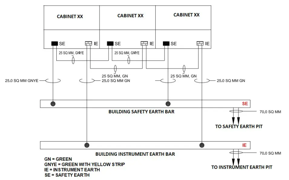
All the instrument earth bars in the cabinets should be connected to a common instrument earth bar provided in the false floor / Cable cellar using an insulated redundant copper conductor cables.
This common Instrument Earth bar shall be further connected to the nearest Instrument earth grid using copper cables.
It should be agreed with the Control system supplier for earthing philosophy of Cabinet’s earth bar connection with the building earth bar network. E.g. Star connection or series connection.
Earthing philosophy should cover Scope of supply, grounding wire/strip sizes, earth stud size, wire color as a minimum.
Series Earth Connectivity
Start / point to point Earth connectivity
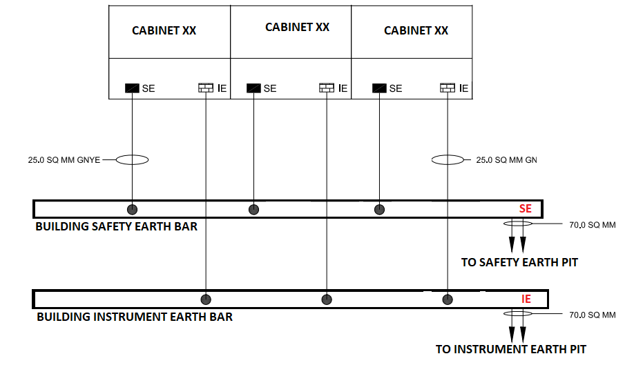
All the safety earth bars in the cabinets should be connected to a common safety earth bar provided in the false floor / Cable cellar using insulated redundant copper conductor cables.
This common Safety Earth bar shall be further connected to the nearest safety earth grid using copper cables. The Main Earth grid conductor size can be calculated based on the desired fault current within the required time to be earthed.
Ultimately, this network/grid is connected to earth pits. The surrounding soil of the earth pit must be kept moist. The effect of the soil temperature on soil resistivity is more influencing near and below the freezing point, which will result in the installation of the earth electrode at the depth to which frost will not penetrate.
Good Practices
- Cable shield shall be insulated and floated at the field instrument side (Cut and Tape). Cable Shield is the drain wire attached with Aluminum Mylar or metal braid cover on the instrument signal cables i.e. 4-20 mA analog signal, low voltage digital signals, etc
- Main cable (i.e. from Junction box and control room) shields shall be grounded at one place i.e. control system end Instrument earth bar Isolated type. All the connections to the Instrument Earth bar within the cabinet shall be of screw type of non-corrosive metal.
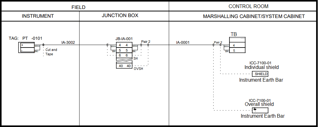
Similarly, for IS cable, individual and overall shield shall be connected to the IS earth bar inside the cabinet.
Ensure continuity of all earth cables up to earth bar & up to earth pits.
- Cable armors shall be earthed at both ends for lightning protection i.e. at the junction box and at the control system end. Since the Junction box body and Control system cabinet body is connected to the Safety earth bar, cable armors are ultimately connected to the safety earth.
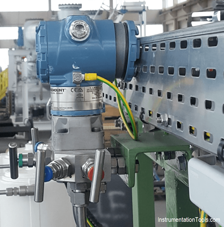
- All instruments (24V DC or 110 V /220V AC operated) body should be earthed to the nearest field safety earth bar located on the Steel structure.
- Earth continuity should be ensured between tray, tray fittings, and tray sections. This will be ensured by Earth cable/strips at every 25 meters of tray length.
- Earth bar connection should be such that painting should not act as bad contact between earth bar and Structure. Continuity shall be ensured.
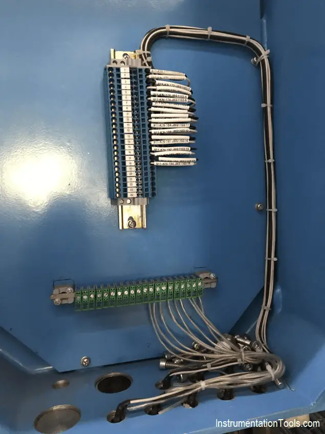
Junction Box Earthing (Safety Earth)
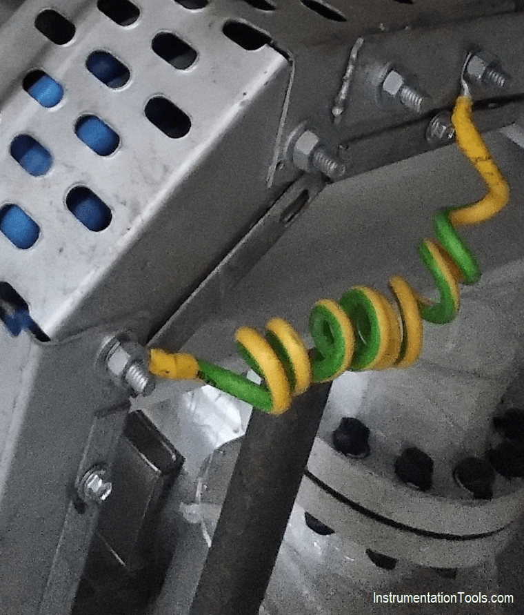
Transmitter Earthing (Safety Earth)
Junction Box shield Termination on Isolated Instrument Earth terminals
Instrument Cable Tray Earthing (Safety Earth)
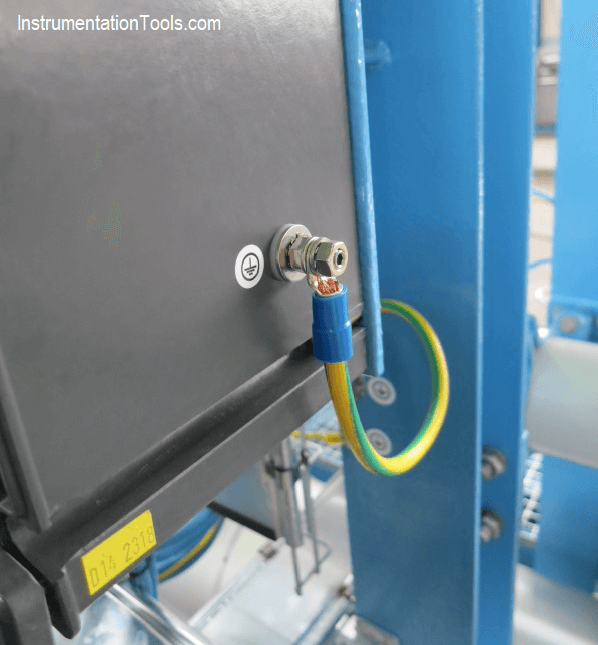
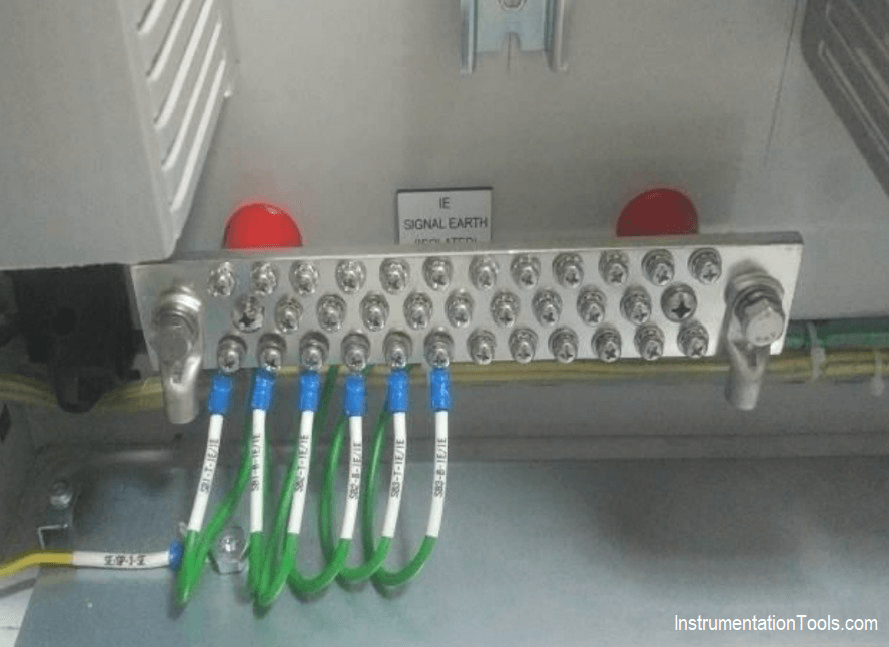
Instrument Earth inside the Control System cabinet (Isolated from Safety Earth)
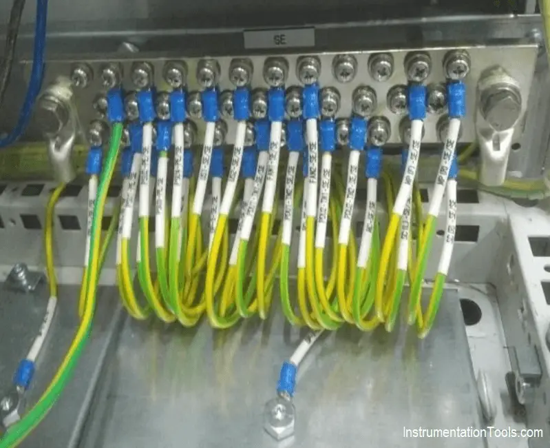
Safety Earth inside the Control system cabinet (Non Isolated)
Author: Jatin Katrodiya
Can you please explain the earthing concept with a diagram ???
what is the value of difference in between Electronic and Electrical earthing ?
The Intrinsically safe earthing approach is only correct if the entire earth or equipotential circuit has a zero potential from end to end, even with an electrical fault present, as per IEC60079 Part 14. In some cases, even at PD of 1 Volt can be incendive. Isolation testing as per the routine maintenance requirements (Part 17), particularly for Zone 0, with grounded instruments is time consuming and costly. Note: Cutting back and insulating the shield in the hazardous area with insulation tape is not permitted, if this is a requirement to conform to Part 14, when using a bond or supplementary bond that could carry fault currents (which can lead to a PD). Always remembering that a shield is one long and large inductor, with very little mutual damping.
We have issue based on earth leakage current that an alarm came du to El detector not get resettled again we check in field side , at jb side they used drain wire comes with mesh armour as a shield and connected which creates all shield having contuinity with Jb ,after we removed both ends shield then alarm clears yet when we put back alarm raises again.
What’s the reason for the alarm can we use the earth wire comes with mesh armour as a shield
Dear sir ,
In above earthing drawing shows drain wire (screen) at instrumnet side is connected .
one of your article in this website stated below .
Why the Cable Screen shall not be Grounded at instrument field device?
Cable screen protects the signal carried on the conductor from external interference. Cable screen blocks the external interference and noise, then directs it to the ground.
Screen shall only be grounded at one source. The grounding is usually made in equipment panel or cabinet while field device point is left ungrounded and insulated.
This is to eliminate the ground-loop current that may arise if screen is grounded at both end. In this case, the ground loop current becomes a noise for the signal conductor itself.Screen shall only be grounded at one source. The grounding is usually made in equipment panel or cabinet while field device point is left ungrounded and insulated.
i am getting confusion please clraify me.
If you earth the cable screen at both the end then there will not any Potential difference.
Yokogawa centum vp ki tarah Honeywell experion epks DCS ka bhi detailed article share kariye..
Please share earth resistance value code reference which reflect less than one ohm
What should be the resistance value between IE bar and SE bar?
size of field instrument earth cable (1core X 6MM2)?
Hi,
As stated in Article 250 of NFPA 70, different types of earthing (intrinsically safe, instrument earth(non IS) and protective earth) shall be connected together (apparently) at one point.
But I didn’t find any solution to avoid one earth current or voltage, affecting other earthing system in any standard.
If I remember correctly, earth bonding is not a common solution in all countries.
With all that being said, here are my questions which I kindly request your help:
1. How to protect for example intrinsically-safe earth system from protective (safety) earth currents when these two earthing systems are connected together? What’s the reference standard and section for the solution provided?
2. If in some other companies, earth bonding is not allowed, what is the reference standard and section?
3. What is pros and cons of each solution?
With many thanks,
Sadeghinia
The IE images does not show a connection on the earth bar to ground. It appears the IE bar is floating. This is dangerous as EMIs could build up and cause electrocution to personnel who come in contact with the screens.