Measuring temperature with RTD / Resistance thermometer
The RTD resistance will change with respect to the temperature. So temperature will be measured by using the RTD resistance.
The simplest way to measure the resistance of a RTD, is to inject a constant current into the RTD and to measure the voltage that develops across the RTD. A Wheatstone bridge circuit, shown in Figure, is however generally used to detect the changes in resistance of a resistance thermometer (RTD).
The values of the fixed resistors, R1,R2 and R3, are very accurately known, while RT represents the resistance of RTD with leads a and b. The bridge is said to be in null balance, when the voltage across points A and B is zero. This occurs when RT = R3×(R1/R2) , causing VAC = VBC, resulting in the reading on Multimeter M, to become zero.
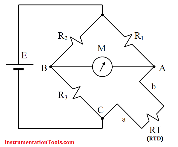
The zero condition would correspond to the zero point or set point of the resistance thermometer (RTD) output. As the temperature increases, the resistance RT, of the resistance thermometer (RTD) will increase, causing the bridge to become unbalanced, and meter M to show a reading. The meter M may be calibrated in temperature units or VAB may be converted into a standard 4 to 20 mA or 1 to 5 V signal.
The current flowing through the RTD must be kept as low as possible (< 1 mA) to minimize errors caused by I2R losses and associated temperature rise in the RTD itself.
Note: 2 wire RTD is considered in the above wheatstone bridge circuit.
Also Read: How Lead Wire Resistance Eliminated in 3 Wire RTD ?