Introduction to Profibus
If Modbus is the “granddaddy” of protocols, then Profibus is the young athlete – lean and fast. Profibus was designed in the 1990s to meet all industrial communication needs for both factory and process automation (Figure 1). As with Modbus, there are a number of terms associated with this protocol: Profibus DP, Profibus PA, Profisafe, Profidrive, and Profinet. One way of visualizing how these terms fit together is to think of Profibus as a book with many chapters. The book would be called Profibus DP (Decentralized Peripheral). The book’s chapters would be called Profibus PA (Process Automation), Profisafe for safety application, and Profidrive for high-speed drive applications. In addition, there would be a second book by the same authors called Profinet, with many chapters, including Profisafe and Profidrive.
Also Read: How Modbus Communication Works
How does Profibus work?
Profibus is also a master-slave type protocol like Modbus but with an additional token ring protocol to allow for multiple masters. Also, unlike Modbus, all devices go through a startup sequence during which they “join” the network. Each slave maintains a failsafe timer. If the master does not talk to it within a certain time limit, the slave goes into a safe state; the master must then go through the startup sequence again before further data exchange can occur. This, in combination with a watchdog timer in the master, ensures that all communication occurs every bus cycle with a certain time value.
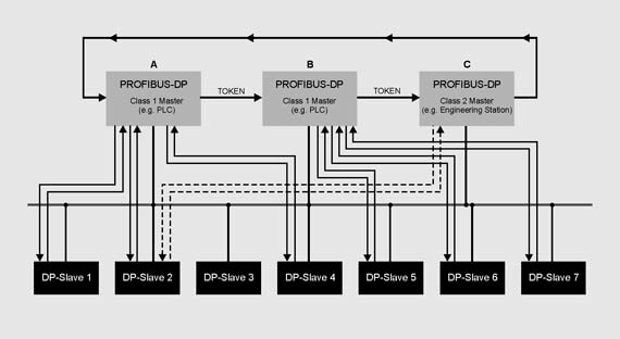
The general bus scan would happen as shown in Figure 2. Master A receives the token, which gives it control of the bus. It will then exchange data with each of its slaves, and when complete, pass on the token to the next master (if there is one). The requirement for detailed diagnostics from each slave is also built into the protocol. During normal data exchange, a slave can alert the master that it has diagnostics, which the master will then read during the next bus scan.
Profinet is built on the same principle as Profibus. But unlike Modbus – which basically took the Modbus RTU packet and encapsulated it into a TCP/IP packet – Profinet was designed to take advantage of Ethernet and permit easy addition of higher-end Profibus functions like Profisafe.
Physical layer
The main physical layer for Profibus DP is based on RS-485, which Modbus uses. However, in the case of Profibus, the Profibus specification does not simply refer to the existing RS-485 specification. Instead, it extends the RS-485 specification. The physical layer was tightened up to require only two wires, with speeds as fast as 12 megabits per second. The Profibus specification also standardized the connectors to be used. All of this is beneficial when working with multiple vendors – wiring is easy and consistent.
For instrumentation, Profibus PA also has another physical layer called IEC 61158-2, Manchester Encoded, bus-powered, intrinsically safe (MBP-IS). This physical layer provides power and communications on the same two wires. The intrinsically safe concept has a big advantage when it comes to installation costs. Working with hazardous environments, there are two approaches: The power going to the instrument in the hazardous area can be contained, or the power going out into the hazardous area can be limited. The containment method is the traditional one and the one that is required for Modbus. It uses a metal conduit and seals to “contain” the energy. Both the conduit and seals are expensive to buy and install. The second approach is used by Profibus PA. It limits the power going to the field and is considered intrinsically safe. With it, no conduits or seals are needed (except maybe at the starting cabinet), resulting in significant cost savings.
Profibus noise immunity
Both of Profibus’ main physical layers (modified RS-485 and MBP-IS) are highly detailed and have excellent noise immunity, proven over and over again at countless sites. Once Profibus is designed and installed properly, it is next to bulletproof.
Standardized outputs and function block design
For instrumentation, there is a part of the Profibus standard called the profile standard, which is a standardization of an instrument from the point of view of the bus. It defines not only standard inputs and outputs, but also functions and functionalities that are within the instrument. This helps in both the setup and integration of field instruments and allows for easy multi-vendor applications.
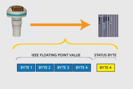
For example, the output from all Profibus PA transmitters is five bytes long. The first four bytes are the IEEE floating point value of the process variable. The fifth byte is the status byte that indicates whether or not the process variable can be trusted. The major status codes are all standardized in the specification. A value of x80, for example, indicates that everything is okay. This applies to all transmitters from all manufacturers [Figure 3]. This significantly lowers the amount of engineering required for device integration. Whereas with Modbus, every device’s data and diagnostics are completely individualized and must be adapted, this is not the case with Profibus.
Use with modems
Profibus DP and Profinet both have tight timing constraints. However, a number of vendors have been able to make a variety of modems (phone lines, wireless, cell) work well with both of them.
Typical applications
Profibus was designed to automate an entire plant, regardless of its size or whether the plant is factory automation (composed of discrete input/output) or process automation (made up of analog input/output). It also does not matter if all the sections are local or remote: Profibus can handle it all well.
Profibus Types
The Profibus family consists of three compatible versions: Profibus-DP, Profibus-PA and Profibus-FMS.
-
- Profibus-DP – Optimized for high speed and inexpensive hookup. DP version is designed especially for communication between automation control systems and distributed I/O at the device level. Can be used to replace parallel signal transmission with 24 V or 0 to 20 mA. This is the only card that will be supported in this specification document.
- Profibus-PA – Designed especially for process automation. It permits sensors and actuators to be connected on one common bus line even in intrinsically safe areas. Permits data communication and power over the bus using 2-wire technology according to the international standard IEC 1158-2. Will not be implemented in this spec because only I/O will be controlled.
- Profibus-FMS – General-purpose solution for communication tasks at the cell level. Powerful FMS services open up a wide range of applications and provide great flexibility. Can also be used for extensive and complex communication tasks. Will not be implemented in this spec because CODE provides much of the same function.
Advantages of Profibus PA
The introduction of PROFIBUS PA has closed the gap of digital data communication between automation systems and field devices. The improved functionality of PROFIBUS PA offers advantages through all stages of a project:
During Installation Phase
Œ Reduced wiring, and therefore, ease of engineering and installation Œ
- Faster assembly and reduced faults Œ
- Material saved for cabling Œ
Instruments can be installed in locations close to the process for direct measurement; information is accessible remotely, daily access is not necessary
During Commissioning Phase
- Œ More than 100 devices can be commissioned per day Œ
- One person can complete commissioning; no need for a second person in the field to find and “activate” an instrument for the loop check Œ
- Communication faults can be located from the control room Œ
- No 4-20mA calibration is required since the digital device measures the full range of process values Œ
- Instrument settings can be downloaded from the control room; no need to connect a handheld to each transmitter individually Œ
During Maintenance Phase
- Diagnostic information for predictive maintenance; maintenance is performed only when scheduled or required Œ
- Determination of process or instrument faults Œ
- Easy and fast troubleshooting from the control room Œ
- No need to find the instrument in the plant Œ
- Fewer trips to the field Œ
- Self-test and corrective functions in the field device Œ
- No periodic 4-20 mA calibration Œ
- Plug and play by downloading replaced instrument settings to the new instrument
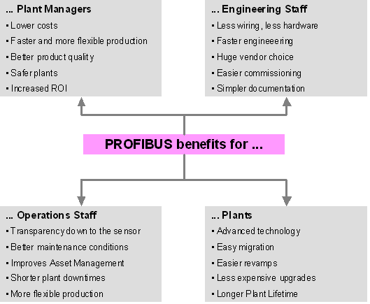
Profibus Benefits