There is much to be said for neatness of assembly in electrical signal wiring. Even though the electrons don’t “care” how neatly the wires are laid in place, human beings who must maintain the system certainly do. Not only are neat installations easier to navigate and troubleshoot, but they tend to inspire a similar standard of neatness when alterations are made.
The following photographs illustrate excellent wiring practice. Study them carefully, and strive to emulate the same level of professionalism in your own work.
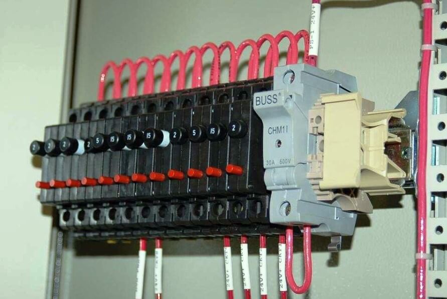
Here we see 120 volt AC power distribution wiring. Note how the hoop-shaped “jumper” wires are all cut to (nearly) the same length, and how each of the wire labels is oriented such that the printing is easy to read:
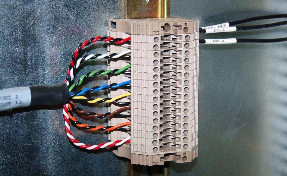
This next photograph shows a great way to terminate multi-conductor signal cable to terminal blocks. Each of the pairs was twisted together using a hand drill set to very slow speed. Note how the end of the cable is wrapped in a short section of heat-shrink tubing for a neat appearance:
Beyond esthetic preferences for instrument signal wiring are several practices based on sound electrical theory. The following subsections describe and explain these wiring practices.
Connections and wire terminations
Many different techniques exist for connecting electrical conductors together: twisting, soldering, crimping (using compression connectors), and clamping (either by the tension of a spring or under the compression of a screw) are popular examples. Most industrial field wiring connections utilize a combination of compression-style crimp “lugs” (often referred to as ferrules or compression terminals) and screw clamps to attach wires to instruments and to other wires.
The following photograph shows a typical terminal strip or terminal block array whereby twisted pair signal cables connect to other twisted-pair signal cables. Metal bars inside each plastic terminal section form connections horizontally, so that wires fastened to the left side are connected to wires fastened to the right side:
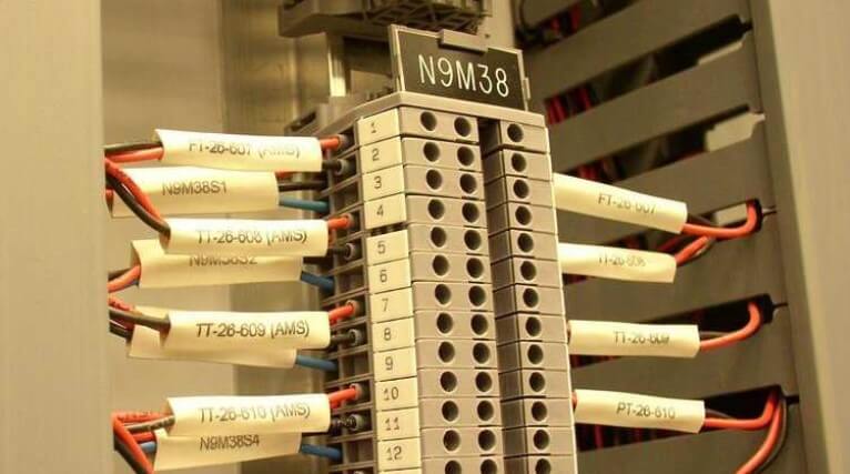
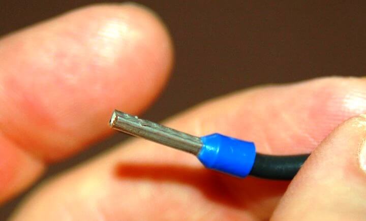
If you look closely at this photograph, you can see the bases of crimp-style ferrules at the ends of the wires, just where they insert into the terminal block modules. These terminal blocks use screws to apply force which holds the wires in close electrical contact with a metal bar inside each block, but metal ferrules have been crimped on the end of each wire to provide a more rugged tip for the terminal block screw to hold to. A close-up view shows what one of these ferrules looks like on the end of a wire:
Also evident in this photograph is the dual-level connection points on the left-hand side of each terminal block. Two pairs of twisted signal conductors connect on the left-hand side of each terminal block pair, where only one twisted pair of wires connects on the right-hand side. This also explains why each terminal block section has two screw holes on the left but only one screw hole on the right.
A close-up photograph of a single terminal block section shows how the screw-clamp system works. Into the right-hand side of this block a single wire (tipped with a straight compression ferrule) is clamped securely. No wire is inserted into the left-hand side:
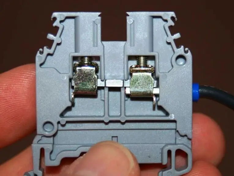
If another wire were secured by the screw clamp on the left-hand side of this terminal block, it would be made electrically common with the wire on the right-hand side by virtue of the metal bar joining both sides.
Some terminal blocks are screwless, using a spring clip to make firm mechanical and electrical contact with the wire’s end:
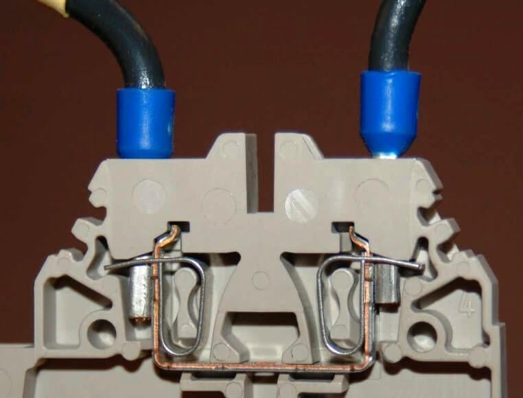
In order to extract or insert a wire end from or to a “screwless” terminal block, you must insert a narrow screwdriver into a hole in the block near the insertion point, then pivot the screwdriver (like a lever) to exert force on the spring clip. Screwless terminal blocks are generally faster to terminate and un-terminate than screw type terminal blocks, and the pushing action of the release tool is gentler on the body than the twisting action required to loosen and tighten screws.
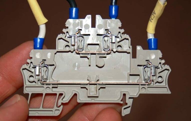
Many different styles of modular terminal blocks are manufactured to suit different wiring needs. Some terminal block modules, for example, have multiple “levels” instead of just one. The following photograph shows a two-level terminal block with screwless wire clamps:
The next photograph shows a three-level terminal block with screw type clamps:
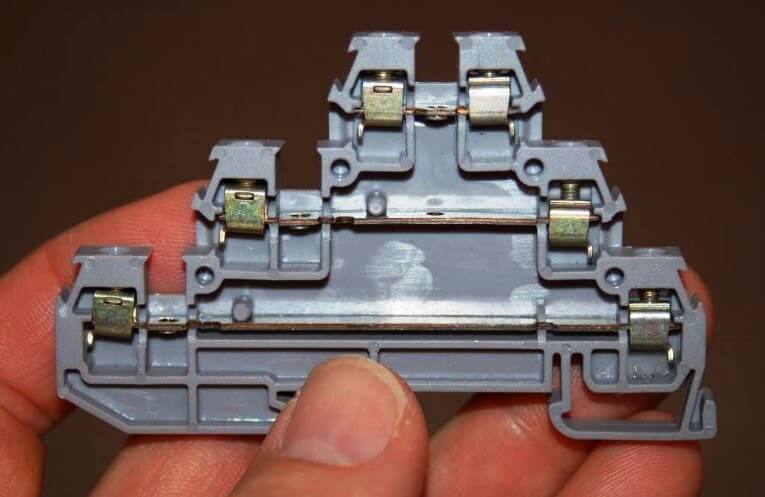
Some multi-level terminal blocks provide the option of internal jumpers to connect two or more levels together so they will be electrically common instead of electrically isolated. This use of a multi-level terminal block is preferable to the practice of inserting multiple wires into the same terminal, when wires need to be made common to each other.
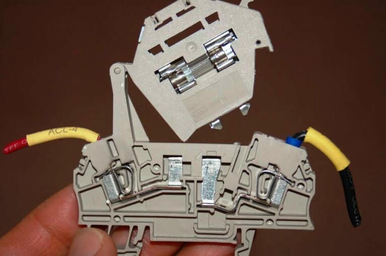
Other modular terminal blocks include such features as LED indicator lamps, switches, fuses, and even resettable circuit breakers in their narrow width, allowing the placement of actual circuit components near connection points. The following photograph shows a swing-open fused terminal block module, in the open position:
Modular terminal blocks are useful for making connections with both solid-core and stranded metal wires. The clamping force applied to the wire’s tip by the screw mechanism inside one of these blocks is direct, with no sliding or other motions involved. Some terminal blocks, however, are less sophisticated in design. This next photograph shows a pair of “isothermal” terminals designed to connect thermocouple wires together. Here you can see how the bare tip of the screw applies pressure to the wire inserted into the block:
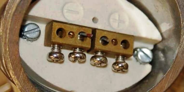
The rotary force applied to each wire’s tip by these screws necessitates the use of solid wire. Stranded wire would become frayed by this combination of forces.
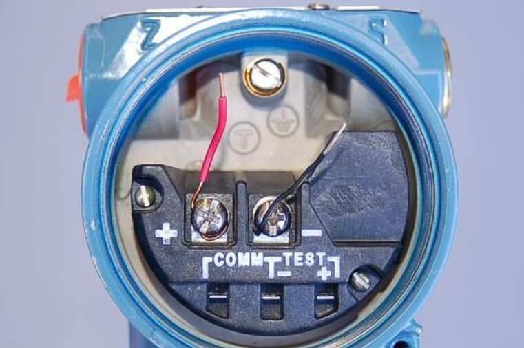
Many field instruments, however, do not possess “block” style connection points at all. Instead, they are equipped with pan-head machine screws designed to compress the wire tips directly between the heads of the screws and a metal plate below.
Solid wires may be adequately joined to such a screw-head connection point by partially wrapping the bare wire end around the screw’s circumference and tightening the head on top of the wire, as is the case with the two short wire stubs terminated on this instrument:
The problem with directly compressing a wire tip beneath the head of a screw is that the tip is subjected to both compressive and shear forces. As a result, the wire’s tip tends to become mangled with repeated connections. Furthermore, tension on the wire will tend to turn the screw, potentially loosening it over time.
This termination technique is wholly unsuitable for stranded wire , because the shearing forces caused by the screw head’s rotation tends to “fray” the individual strands. The best way to attach a stranded wire tip directly to a screw-style connection point is to first crimp a compression style terminal to the wire. The flat metal “lug” (ferrule) portion of the terminal is then inserted underneath the screw head, where it can easily tolerate the shearing and compressive forces exerted by the head.
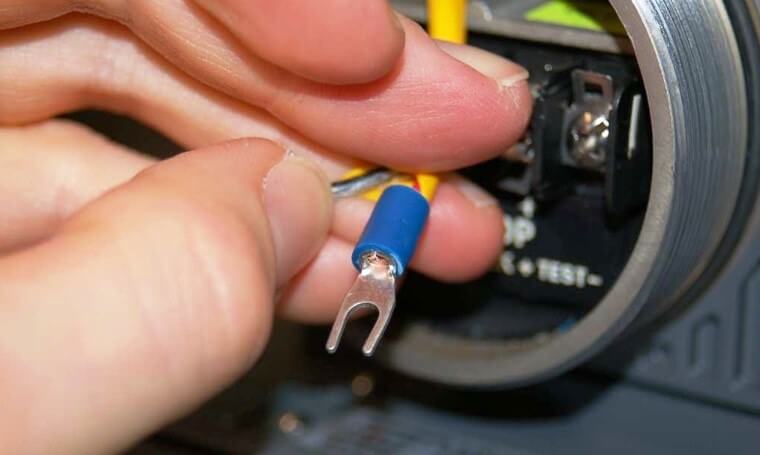
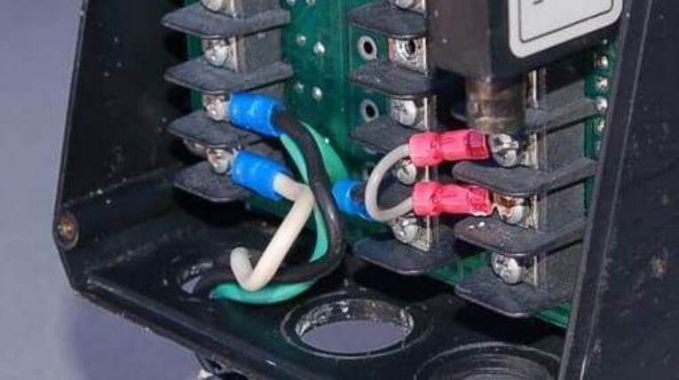
This next photograph shows five such stranded-copper wires connected to screw-style connection points on a field instrument using compression-style terminals:
Compression-style terminals come in two basic varieties: fork and ring. An illustration of each type is shown here:
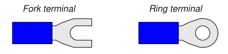
Fork terminals are easier to install and remove, since they merely require loosening of the connector screw rather than removal of the screw. Ring terminals are more secure, since they cannot “fall off” the connection point if the screw ever accidently loosens.
Just as direct termination underneath a screw head is wholly unsuitable for stranded wires, compression-style terminals are wholly unsuitable for solid wire. Although the initial crimp may feel secure, compression terminals lose their tension rapidly on solid wire, especially when there is any motion or vibration stressing the connection. Compression wire terminals should only be crimped to stranded wire!
Properly installing a compression-type terminal on a wire end requires the use of a special crimping tool. The next photograph shows one of these tools in use:
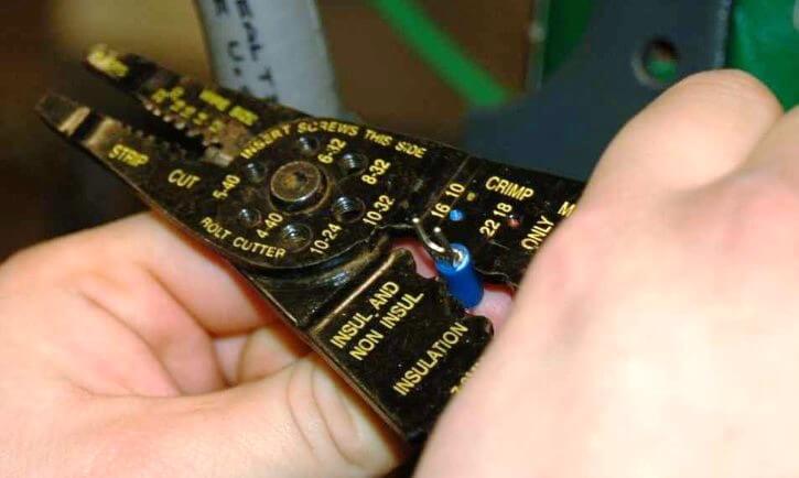
Note the different places on the crimping tool, labeled for different wire sizes (gauges). One location is used for 16 gauge to 10 gauge wire, while the location being used in the photograph is for wire gauges 22 through 18 (the wire inside of the crimped terminal happens to be 18 gauge). This particular version of a “crimping” tool performs most of the compression on the underside of the terminal barrel, leaving the top portion undisturbed. The final crimped terminal looks like this when viewed from the top: