Control valves play a major role in the everyday effort to increase process plant profitability and conserve energy.
Proper selection of these valves can have a significant financial impact on the overall cost of a project and how well the process can be controlled.
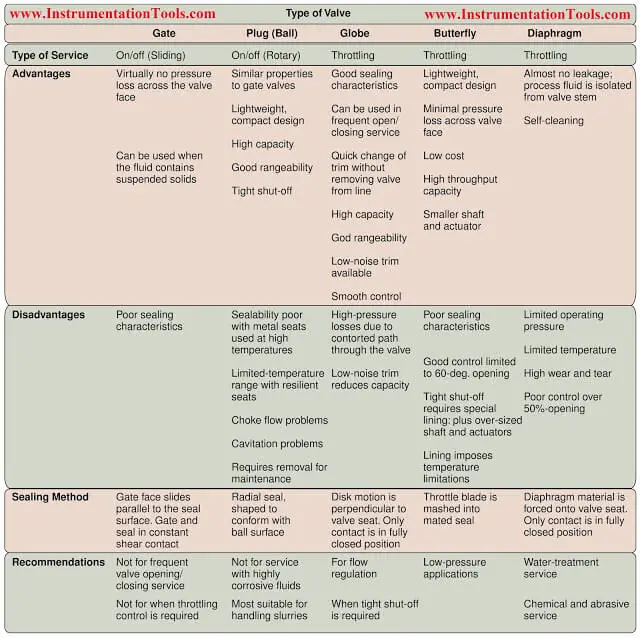
Control Valve Selection Guide
To narrow down the choices, the engineer must understand how the general characteristics of each type of valve match up with the design requirements of the valves.
Controlling the valve
A control loop consists of a sensing element, a controller and the final control element — the valve and its actuator. The sensing element transmits a signal to a single controller or a distributed control system (DCS).
The controller compares the signal with the setpoint, and then makes any needed corrections by sending a signal to the control valve. The correction is measured and verified by the sensing element, completing the loop.
In below Figure, the I/P transducer changes an electronic signal into one that is pneumatic. A control valve should react instantaneously to any change in the signal.
To be effective, a valve should: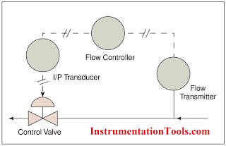
- operate over a wide range of flows (have a wide rangeability);
- accurately respond to any signal across its operating range;
- exhibit little dead time or hysteresis;
- react to incremental adjustments from the controller (resolution); and
- respond with the required speed (stroking speed).
- A fast response may not be suitable for all applications.
For example, a quick or sudden reduction in the bore of a valve in a pipeline may be harmful, causing a shock wave. A valve’s ability to control flow depends upon the quality of its actuator.
A positioner may be added to obtain tighter control. Positioners improve performance by amplifying the controller’s signal, thereby achieving a more-precise response. This also helps to overcome the effects of any valve-stem friction and improve shut-off.
The quality of any control device can be quantified in terms of its gain, time constant and dead-time lag. Of these, the gain is the most important for a control valve. Gain is the ratio of the percentage change in a process variable to the percentage change of the valve travel. Gain depends upon the valve characteristics and process conditions.
Design parameters
To properly select a control valve, the following fluid and system properties must be known: its state (vapor, liquid or two-phase), vapor pressure, flowrate, inlet and outlet pressures, inlet temperature, density, molecular weight, viscosity, specific heat ratio, critical temperature and critical pressure.
The maximum flowrate that is specified should include an appropriate design margin (typically, 10%). Specification calls for knowing the system’s geometry, size and pipe schedule number, and materials of construction, as well as the valve’s fail-safe position, maximum shut-off pressure and the percent flash (for flashing fluids) through the valve.
Since a control valve is power-operated, the engineer must consider its response to loss of signal or power — i.e., the valve’s fail-safe mode. In about 80% of applications, control valves are specified to fail closed. However, sometimes, the valve should either fail open, lock (fail-in lock position) or drift (slowly, to either close or open).
A fail-open valve would be needed in a deluge system, for instance. Springs within the bonnet normally enable the actuator to reach the failure position. In some cases, such as for a lock position or a fail drift, an auxiliary power source (e.g., an air cylinder) may be required. Safety codes and concerns, and process requirements will determine the failure position.
Flow coefficient
The most important valve parameter for calculating the size of a control valve is the flow coefficient, Cv.Calculation of Cv depends upon whether the flow is incompressible, compressible or mixed-phase.
There are equations for determining Cv for incompressible, compressible, two-phase, and cavitating or flashing fluids. These references allow a preliminary valve size to be computed.
Trim and bonnet
Trim : refers to the removable, internal parts of the valve that are in contact with the flowing fluid. Parts not considered as trim include the packing, bonnet, bottom flange and gaskets. The trim maintains the relationship between the flow capacity and valve-plug lift, and ensures proper shut-off of the valve.
The seat is primarily responsible for the tightness of shut-off. Correct lift and tight shut-off are also affected by other parts of the valve, such as body shape, actuator design and valve-stem packing. The required level of tightness of shut-off depends upon the type of service. Shut-off is measured by the percentage of total flow that leaks through when the valve is closed. There are industry standards that define the shut-off requirements for various applications.
A common standard that defines leakage classes is “Control Valve Seat Leakage,” ANSI/FCI 70-2-1998 (3). The classes range from a weak shut-off (Class II) to nearly zero leakage (Class VI). (Class I does not have any standards or leak rate associated with it.) Depending on the requirements, the user then sets the tight shut-off (TSO) requirement as one of the shut-off classes (normally IV, V or VI).
Valve trim selection is primarily based on the fluid operating conditions, the manufacturer’s inherent flow characteristic for a particular trim, and the effect on the inherent flow characteristic at different operating conditions. These parameters enable prediction of the installed flow characteristic for each trim, which is used as a basis for trim selection.
Reduced-capacity trim helps to attain precise control at low flows, while leaving room for higher flows in the future. Such trim is designed so that flow through the port is lessened, but the precision of the flow control is increased because of a reduced plug-lift distance.
There is no general rule that states reduced trim should be used below a certain turndown rate. However, reduced trim may be a solution when precise control is required at 20–25% of valve capacity.
Cages are common in trim and serve multiple purposes:
- A cage serves as a guide for the plug, ensuring that it is properly positioned and makes the right contact with the seat.
A characterized cage can be used to alter the installed flow characteristics of the valve. The shape of the orifices cut into the cage determine whether a valve is equal-percentage, linear or quick-acting. - The cage can be designed to ensure a balanced spread of liquid forces on the plug and stem, resulting in what is known as a cage-guided, balanced trim.
The plug and stem in a sliding-stem valve experience forces that affect the actuator‘s control of the plug, and result in jerky, inaccurate stem motions and high dead-bands.
The fluid around the stem can push it up, down or sideways, and even impart torsional forces on it. There are trim designs that counteract and balance these forces. A balanced trim uses mechanical modifications to the plug or a cage trim to spread and even out the forces.
Bonnet :
Special consideration must also be given to the bonnet, which encases the actuator and the valve packing. Bonnets are often designed to meet certain temperature ranges.
For high (e.g., 450°F) and below freezing temperature service, an extension bonnet is used. This bonnet isolates the packing from extreme temperatures.
In cryogenic service, the extension separates the valve-stem packing from the sub-zero fluid, preventing the packing from becoming brittle. An externally finned bonnet is sometimes used for high temperatures. The fins promote heat loss to the ambient air.
Noise :
Control valves generate noise due to mechanical vibrations, cavitation or aerodynamic effects. High velocities, pressure oscillations and unsteady flow create vibrations that are usually under 100 decibel (dB), the intensity of sound at maximum level from the earphones of a portable radio. (Normal conversation is about 60 dB, and the eardrum’s pain threshold is around 130 dB.)
The noise generated by cavitation depends upon its degree. Increasing the pressure drop across a valve will increase the noise. During full cavitation, a control valve makes a rattling noise.
However, the noise is usually under 100 db. Aerodynamic-generated noise results from the mixing of turbulent fluids with laminar ones. This is the most common and worst source of noise — levels can reach over 100 db. The noise limitations for the process need to be specified to the valve supplier
Selecting the type of valve
Valve manufacturers will provide actual valve flow capacity, expressed in terms of Cv, for their various valve sizes and types. Once a valve type and flow characteristic are established, a preliminary size can be determined by computing the valve stroke for each design flow case.
The stroke is the ratio of the calculated Cv to the actual Cv for a particular valve. Choose a valve that can operate between 10–80% of the valve stroke across the expected range of operation, i.e., the minimum, normal and maximum flowrates.
Rules of thumb for sizing and selection
The following should be used as a guidelines, but not as design criteria :
- In a pumped circuit, the pressure drop allocated to the control valve should be equal to 33% of the dynamic losses in the system at the rated flow, or 15 psi, whichever is greater.
- The pressure drop allocated to a control valve in the suction or discharge line of a centrifugal compressor should be 5% of the absolute suction pressure, or 50% of the dynamic losses of the system, whichever is greater.
- In a system where static pressure moves liquid from one pressure vessel to another, the pressure drop allocated to the valve should be 10% of the lower-terminal vessel pressure, or 50% of the system’s dynamic losses, whichever is greater.
- Pressure drops in valves in steam lines to turbines, reboilers and process vessels should be 10% of the design absolute pressure of the steam system, or 5 psi, whichever is greater.
- The gain on a control valve should never be less than 0.5.
- Avoid using the lower 10% and upper 20% of the valve stroke. The valve is much easier to control in the 10–80% range.
- Generally, control-valve bodies are one size less than the line size. If this causes the valve body to be significantly less than the line size, which would reduce the valve’s effective Cv. then do not apply this generalization.
Flow characteristic selection
Here are some guidelines that are helpful in deciding which type of flow characteristic is best-suited for a particular application.
These are guidelines only, and should not be taken as absolute recommendations:
Equal percentage:
- when the major portion of the control-system pressure drop is not through the valve
- for temperature- and pressure-control loops Linear:
- in liquid-level or flow-control service
- where the pressure drop across the valve is expected to remain fairly constant
- where the major portion of the control system’s pressure drop is through the valve.
Quick-opening:
- for frequent on/off service, such as in batch or semi-continuous processes, or where an “instantly” large flow is required, i.e., for safety or deluge systems.
Materials of construction
Materials selection includes specifying the hard body, trim, soft gasket, seal and packing materials. As a minimum requirement, the body and trim should match the material of the interconnecting piping.
In addition to customer preferences and cost considerations, the nature of the fluid also affects material selection. Be careful when handling erosive and corrosive fluids.
Erosion may be slowed by hard-facing the valve internals with nickel or cobalt-chromium alloys. Considerations must be given for high- and low-temperature services (>800°F and below freezing, respectively).
For example, at high temperatures, valves are subject to greater stress and leakage due to the expansion of their internals. Liquids that flash through a control valve may cool to subzero temperatures. This is especially so when throttling highpressure hydrocarbon liquids.
A flash calculation must be performed to check for the outlet temperature at the lower pressure. In other low-temperature service, such as with cryogenic liquids, atmospheric moisture can cause the moving components of the valve, such as the stem, to freeze, rendering them inoperable.
Thus, these valves require insulation. The valve body and the packing should be designed to withstand high pressure. In high-pressure application (> 1,000 psi), graphite is used to reinforce soft packings to prevent extrusion through small orifices.
Reduced-port valves are used more often than full-size ports, because the former creates a pressure drop to attain the correct Cv. Also, a reduced port is less expensive since it fits into a smaller body. Avoid specifying odd sizes of valves, for example, 1.25, 2.5, 3.5, 5 and 22 in. These less-common sizes are hard to find and cost more than standard sizes.
Valves can be fitted with different end connections. The RF (raised face) is commonly used; the RTJ (ring-type joint) is found in some of the high-pressure classes. Valves can be welded into place, providing a leak-free connection This eliminates the cost and weight of flanges, but may be problematic if the valve has to be removed for service.
Maintenance
Obviously, a poorly designed valve may require more maintenance because it will be unable to function adequately under the service conditions. Common problems are wear of the valve body, actuator diaphragm, seat and packing. Each one of these can be reduced by selecting the proper style of valve and its materials of construction.
For example, a valve handling entrained solids has to be cleaned more often to remove debris. In this instance, selecting a globe valve may not be advisable, as debris can be drawn through the stem seal, thus damaging it and restricting control. A rotary valve may be a better choice.
Packing wear is caused by friction between the packing and the valve stem. A sliding-stem valve can often result in more wear than one with a rotary stem, since the sliding stem can collect deposits, and may drag them through the packing. Packing wear is amplified in valves with a poor stem surface-finish, due to high friction between the rough stem and the packing.
Selection of a valve with a smoother stem surface can help. The valve seat may suffer damage from two sources: the flowing fluid and the plug itself. A soft seat, sometimes necessary for tight shut-off, can be eroded away if exposed to a fluid with entrained solids.
A metal seat is recommended for such service, otherwise, the soft seal should be placed such that it is shielded from the main flow path. If the plug and the seat are not in good contact, lapping the seat may be a good option. Lapping, which applies only to metal seats, a process where the plug and seat are manually ground together so that they have a matching surface finish, and, thus, tighter fit. Selecting valves with some diagnostic features may help to reduce maintenance.
Smart valves and positioners relay valve signature parameters (actuator pressure, stem travel, etc.) to software, which uses them to calculate performance indicators, such as packing-stem friction and torque.
Monitoring the signature can help to predict maintenance requirements. To be on the safe side, consult with maintenance and operations personnel during valve selection and design.
A final caution: Sizing the valve properly is important for both process and economical efficiency. A widespread industry problem is the over-sizing of control valves, which leads to poor control and reduced service life.
Thank dear sir for provide excellent knowledge….
In “Flow characteristic selection/Equal percentage:” , WHY THE FIRST GUIDELINE & THE LAST ONE ARE VICE-VERSA?